Systems and methods for assisting with internal positioning of instruments

a technology of internal positioning and imaging, applied in the field of internal procedures, can solve the problems of difficult identification of instruments within real-time ultrasound images, complex and expensive equipment, and difficult capture and display in ultrasound images, etc., to facilitate high-resolution movement detection, facilitate improved movement detection, and facilitate the effect of simple configuration

Active Publication Date: 2013-09-03
FUJIFILM SONOSITE
View PDF7 Cites 31 Cited by
  • Summary
  • Abstract
  • Description
  • Claims
  • Application Information

AI Technical Summary

Benefits of technology

[0015]A mechanical instrument interface of an opto-mechanical sensor system of embodiments is adapted to engage a surface of an instrument and to provide mechanical motion corresponding to movement of the instrument. Accordingly, mechanical instrument interfaces of embodiments of an opto-mechanical sensor system include an interface surface for interfacing with a surface of an instrument and a sensor surface for facilitating operation of a corresponding optical sensor system of the opto-mechanical sensor system.
[0018]Embodiments of the mechanical instrument interface are adapted to accommodate different instrument configurations (e.g., different needle gauges). For example, a mechanical instrument interface may use a movable or adjustable mechanical instrument interface mount to accommodate different needle gauges. Additionally or alternatively, embodiments of the mechanical instrument interface provide a motion multiplier, such as to facilitate improved movement detection by a corresponding optical sensor system, to facilitate high resolution movement detection, etc. For example, the mechanical instrument interface may be adapted such that the sensor surface moves at a higher velocity than does the corresponding interface surface to thereby provide a motion multiplier.
[0019]The mechanical instrument interface of opto-mechanical sensors of embodiments is adapted to provide a relatively inexpensive, simple configuration. For example, a mechanical instrument interface may be comprised of few pieces, such as small molded plastic pieces, metal pieces, etc. Such embodiments facilitate disposal of the mechanical instrument interface after use. Thus, although the mechanical instrument interface may be used within the sterile field of a particular procedure, sterility may be maintained through sterilization of the unit at manufacture and its disposal after use. A mechanical instrument interface utilized according to embodiments of the invention may additionally or alternatively be adapted to facilitate its sterilization and reuse.
[0021]Commercially available, off-the-shelf optical sensor components are preferably utilized in providing an optical sensor system of embodiments of the present invention. For example, commercially available sensor packages comprising an image acquisition system (IAS), associated digital signal processor (DSP), and other components are utilized in implementing an optical sensory system for use in instrument movement determination according to embodiments of the invention. Accordingly, low cost, highly miniaturized optical sensor systems may readily be provided to facilitate their unobtrusive disposition on various equipment (e.g., instrument guides, ultrasound transducer assemblies, etc.), disposability (e.g., for use in sterile environments), etc.
[0024]The foregoing position information may be utilized in combination with an ultrasound image generated by an ultrasound system unit to display a visual representation of the instrument, or portion thereof, within a object being imaged (e.g., portion of a patient's internal physiology). For example, the calculated position of a portion of the instrument within the object may be superimposed onto an image generated using the imaging transducer, thereby allowing a clinician or other user to visualize the placement of the instrument.
[0026]Opto-mechanical sensor systems of embodiments of the invention may be utilized in combination with other instrument position detection or determination systems, if desired. For example, an opto-mechanical sensor system of an embodiment may be utilized in combination with an enhanced instrument imaging technique (e.g., an imaging technique operable to more consistently obtain images of portions of an instrument) in order to provide higher levels of confidence for instrument location determination, to provide present location determination correction, etc.

Problems solved by technology

The technique, however, is quite complicated and requires complex and expensive equipment which is limited in use to needle location estimation.
Regardless of whether an out-of-plane or in-plane technique is used, it is often very difficult to identify the instrument within a real-time ultrasound image.
For example, instruments such as needles and catheters are relatively small and thus difficult to capture and display in an ultrasound image.
Moreover, various structure and features within the object being imaged may obscure the instrument, or portions thereof.
Even where a portion of the instrument is captured and displayed in an ultrasound image it is often difficult for a clinician to readily identify the instrument within the displayed image.
However, the vibratory device is somewhat cumbersome and difficult to utilize in combination with needle insertion.
Moreover, the technique results in somewhat imprecise depiction of the needle position because the color Doppler image modes used to display the needle vibration artifacts are generally of relatively low resolution which, particularly when combined with the vibration of the needle.
Unfortunately, the lighting and other ambient conditions present during a procedure may not be conducive to an accurate count of such gradations.
Moreover, a clinician performing a procedure is often unable to view the needle for sufficient periods of time to accurately count the passing of all gradations.
Such facets have not, however, been found particularly effective in identifying particular portions of the needle, such as the tip.
Moreover, the presence of the facets upon the surface of the needle affects the use of the needle, such as by causing insertion resistance, patient discomfort, etc.
However, such a technique is often undesirable due to risks associated with injecting such media into a patient and the complexity added to the procedure associated with the use and delivery of such contras agents.
Such techniques, however, are often undesirable due to the expense and complexity added to the procedure associated with the use of such special purpose instruments.
However, the very small transducer and its associated control circuitry is relatively expensive and of use only for such procedures.
However, these adaptations introduce undesired complexity, risk, and cost to the procedure.

Method used


Image

  • Systems and methods for assisting with internal positioning of instruments
  • Systems and methods for assisting with internal positioning of instruments
  • Systems and methods for assisting with internal positioning of instruments

Examples


Embodiment Construction

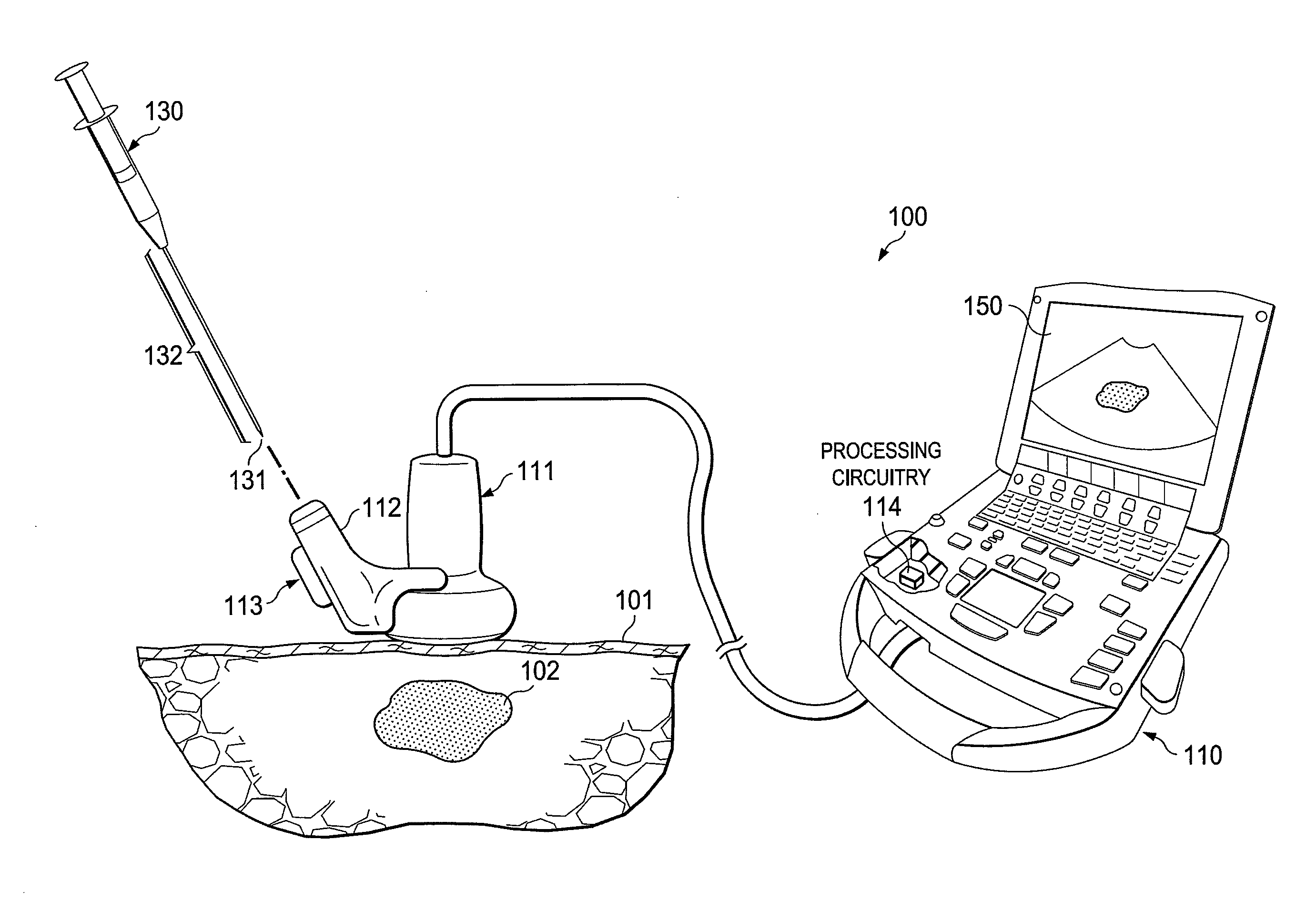
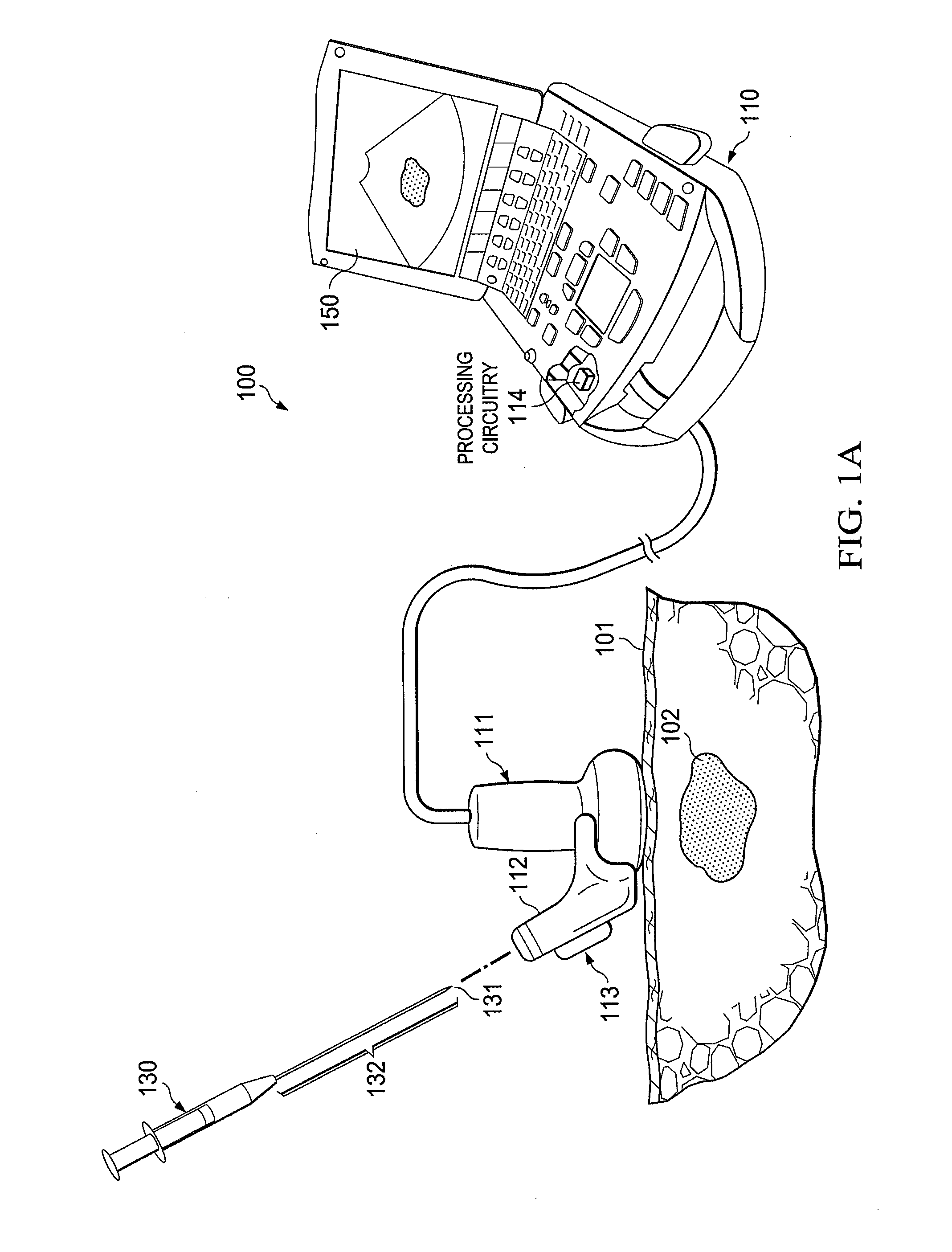
[0034]FIG. 1A shows an imaging system adapted according to an embodiment of the invention to determine the position of an instrument (such as a needle, catheter, stent, endoscope, angioplasty balloon, etc.), or a portion of an instrument (e.g., a needle tip) within an object using an opto-mechanical sensor system configuration. Specifically, imaging system 100 of FIG. 1A, such as may comprises an ultrasound imaging system, is adapted for use in providing real-time images for facilitating positioning a portion of instrument 130 within object 101. For example, instrument 130 may comprise a needle or other interventional instrument for insertion into object 101, such as may comprise a human body, for interfacing with one or more objects therein, such as target 102 (e.g., a cyst, tumor, blood vessel, nerve, etc.), during an interventional procedure (e.g., biopsy, injection, line insertion, etc.).

[0035]The term real-time as used herein, such as for real-time images, is intended to encomp...


PUM


Abstract

Systems and methods which determine the position of an instrument internal to an object using an opto-mechanical sensor are shown. Embodiments utilize an opto-mechanical sensor system in which a mechanical instrument interface provides instrument movement information to a corresponding optical sensor system to determine instrument movement. Determinations of instrument movement preferably provide information regarding movement direction and speed. Such information, when used in combination with other information such as starting position or starting position offset, insertion angle or angle of attack, and / or insertion plane, is utilized by embodiments of the invention to determine the position of an instrument or portion thereof. Embodiments are adapted to accommodate different instrument configurations. Position information may be utilized in combination with an ultrasound image to display a visual representation of the instrument, or portion thereof, within a object being imaged.

Description

CROSS-REFERENCE TO RELATED APPLICATIONS[0001]The present application is related to co-pending and commonly assigned U.S. patent application Ser. No. 12 / 752,595 entitled “Systems and Methods to Assist with Internal Positioning of Instruments,” filed Apr. 1, 2010, Ser. No. 12 / 790,109 entitled “Systems and Methods for Enhanced Imaging of Objects Within an Image,” filed May 28, 2010, and Ser. No. 12 / 752,530 entitled “Systems and methods for Using Imaging to Assist with Internal Positioning of Non-Modified Instruments,” filed Apr. 1, 2010, the disclosures of which are hereby incorporated herein by reference.TECHNICAL FIELD[0002]This disclosure relates to techniques for aiding internal procedures and, more particularly, to systems and methods for using imaging to assist with internal positioning of instruments.BACKGROUND OF THE INVENTION[0003]Many medical procedures require precise positioning of an instrument internal to a patient. For example, interventional instruments, such as needles...

Claims


Application Information

Patent Timeline
Patent Type & Authority Patents(United States)
IPC IPC(8): A61B5/05A61M5/00A61B8/00
CPCA61M5/427A61M5/46A61B8/4455A61B8/463A61B8/467A61B2017/3413A61B8/461
Inventor WILLIAMS, KEITHDUNHAM, PAUL THURMANMARQUIS, STEVEN RUSSELL
Owner FUJIFILM SONOSITE
Why Eureka
Try Eureka