
Polymeric electret film and method of manufacturing the same

a polymer electret and film technology, applied in the field of electret, can solve the problems of complex charging phenomena, difficult to retain surface charges, and inability to reorient electrical polarization, and achieve the effect of improving the polarized initial surface potential and lowering the surface potential decay ra

Active Publication Date: 2013-09-10
EF MATERIALS IND
View PDF8 Cites 5 Cited by
  • Summary
  • Abstract
  • Description
  • Claims
  • Application Information

AI Technical Summary

Benefits of technology

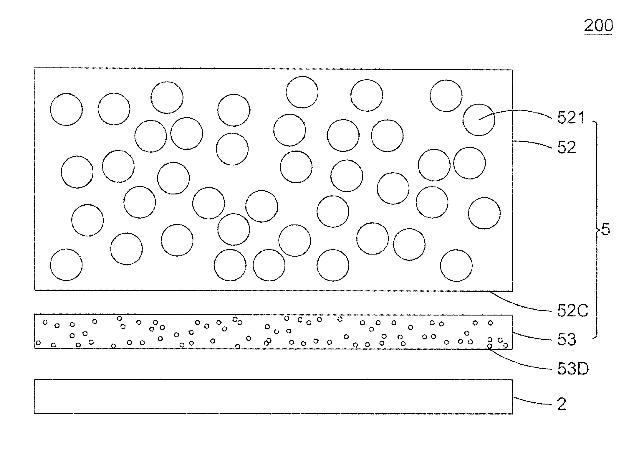
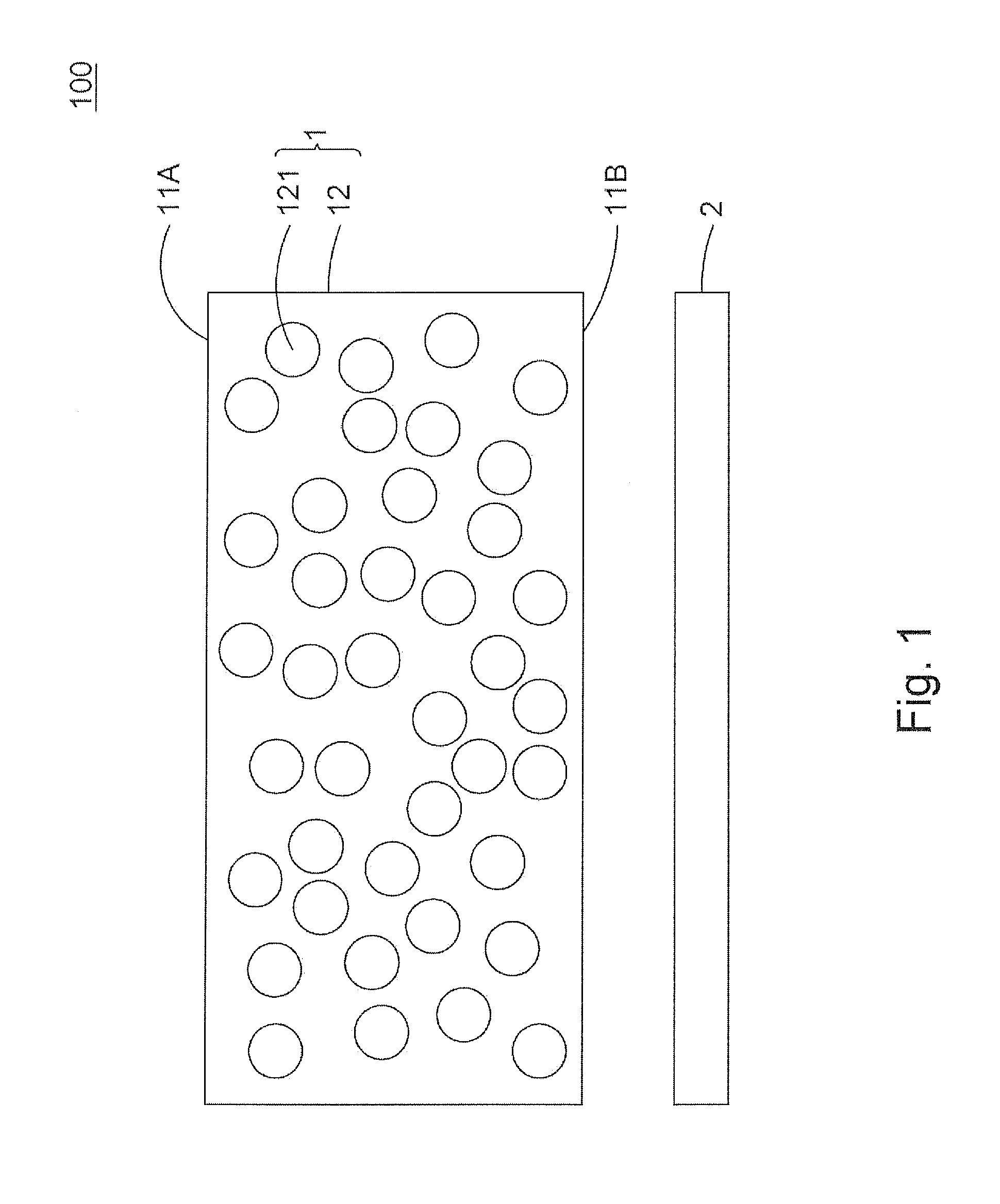
[0021]Accordingly, the primary object of the present invention is to provide a polymeric electret film and method of manufacturing the same. The polymeric electret film comprises a polytetrafluoroethylene film and an electrode layer. The polytetrafluoroethylene film includes a porous layer, which has a porous structure. The porous structure has a pore diameter ranging between 0.01 μm and 5.0 μm and has a porosity ranging between 20% and 95%. The polytetrafluoroethylene film has a thickness ranging between 1 μm and 50 μm, and is preferably made of expanded porous polytetrafluoroethylene. The obtained polymeric electret film is capable of improving the polarized initial surface potential and lowering the surface potential decay rate.

Problems solved by technology

In dipolar electrets, the reorientation of electrical polarization can only be achieved at temperatures where the dipoles are mobile.
As being exposed to the ambient environment, surface charges are difficult to retain and usually temporarily stay on the dielectric materials.
However, the use of external electrodes results in air gaps at the dielectric / electrode interface that can lead to very complicated charging phenomena.
High-energy electron and ion beams (i.e. ionizing radiation) do not work well for electret charging because of the chemical damage caused to most dielectric materials as a result of radiation exposure.
The damage leads to induced conductivity that destabilizes the implanted charge leading to recombination of positive and negative centers.
Under the room temperature, the type of electrets dominates how its polarization remains while a relatively high temperature can lead to quick decay of electret's charge storage volume.
Hence, it would be an important issue to improve decay of electret's charge storage volume in high-temperature environment.
Traditionally, while hydrocarbon polymer materials, such as polypropylene, polyethylene or polycarbonate, are relatively inexpensive and processible, and have good chemical resistance as well as mechanical properties, as electrets, they suffer from serious decay of charge storage volume and shortened service life, thus being incompetent for long-term effective applications.
Perfluoropolymers, such as fluoropolymers, fluorinated ethylene-propylene (FEP) and polytetrafluoroethylene (PTFE), do have long-term stability, but are expensive and insoluble to solvents, thus being less processible and having their application scope limited.
However, U.S. Pat. No. 5,384,337 does not disclose any data regarding surface potential decay, resulting in the performance of the electrostatic porous material remaining unknown.

Method used


Image

  • Polymeric electret film and method of manufacturing the same
  • Polymeric electret film and method of manufacturing the same
  • Polymeric electret film and method of manufacturing the same

Examples


experimental example 1

[0073]Please refer to both FIGS. 6A and 6B. The polymeric electret film 100 of the present experimental example 1 is a polymeric electret film 100 according to the first preferred embodiment of the present invention.

[0074]Therein, the polytetrafluoroethylene film 1 of the polymeric electret film 100 was made of expanded porous polytetrafluoroethylene as described previously in the first preferred embodiment.

[0075]In addition, the experimental example 1 also adopted polytetrafluoroethylene and fluorinated ethylene-propylene as the material of which the polytetrafluoroethylene film 1 was made of.

[0076]Accordingly, there were three types of the polymeric electret film 100 in the experimental example 1, including:[0077]1. Sample A: the polytetrafluoroethylene film 1 made of expanded porous polytetrafluoroethylene, with a thickness of 15 μm;[0078]2. Sample B: the polytetrafluoroethylene film 1 made of polytetrafluoroethylene, with a thickness of 15 μm; and[0079]3. Sample C: the polytetra...

experimental example 2

[0089]Please refer to both FIGS. 7A and 7B. The polymeric electret film 100 of the present experimental example 2 is a polymeric electret film 100 according to the first preferred embodiment of the present invention.

[0090]Therein, the polytetrafluoroethylene film 1 of the polymeric electret film 100 was made of expanded porous polytetrafluoroethylene as described previously in the first preferred embodiment.

[0091]In addition, the experimental example 2 also adopted polytetrafluoroethylene and fluorinated ethylene-propylene as the material of which the polytetrafluoroethylene film 1 was made of.

[0092]Accordingly, there were three types of the polymeric electret film 100 in the experimental example 2, including:[0093]1. Sample D: the polytetrafluoroethylene film 1 made of expanded porous polytetrafluoroethylene, with a thickness of 25 μm;[0094]2. Sample E: the polytetrafluoroethylene film 1 made of polytetrafluoroethylene, with a thickness of 25 μm; and[0095]3. Sample F: the polytetra...

experimental example 3

[0102]Please refer to both FIGS. 8A and 8B. The polymeric electret film 100 of the present experimental example 3 is a polymeric electret film 100 according to the first preferred embodiment of the present invention.

[0103]Therein, the polytetrafluoroethylene film 1 of the polymeric electret film 100 was made of expanded porous polytetrafluoroethylene as described previously in the first preferred embodiment.

[0104]There were two types of the polymeric electret film 100 in the experimental example 3, including:[0105]1. Sample A: the polytetrafluoroethylene film 1 made of expanded porous polytetrafluoroethylene, with a thickness of 15 μm; and[0106]2. Sample G: the polytetrafluoroethylene film 1 made of polytetrafluoroethylene, with a thickness of 10 μm; and

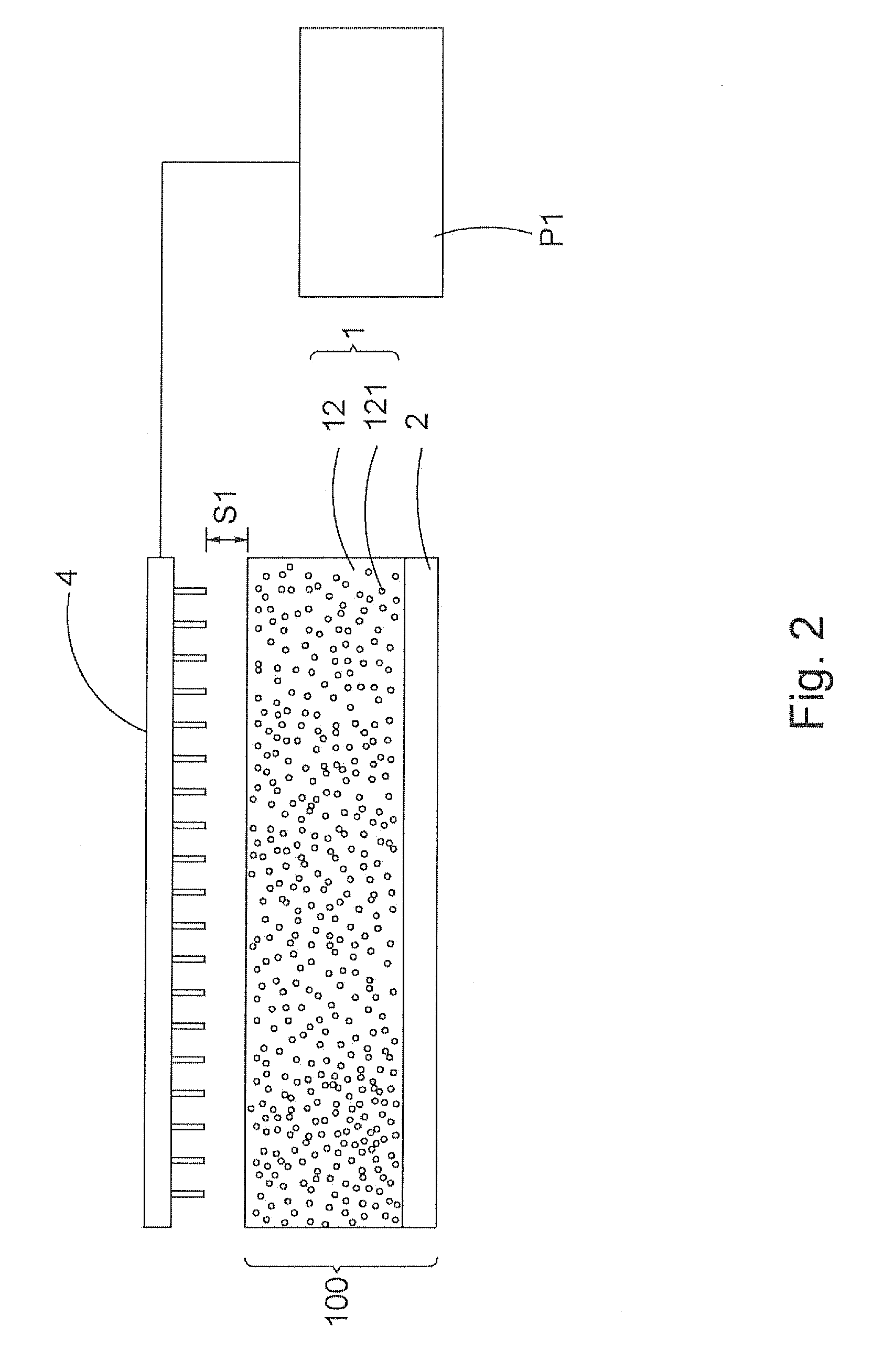
[0107]After Sample A and Sample G were prepared by the process described in the first preferred embodiment, the corona charging method was conducted thereto, respectively. Therein, the parameters for the corona charging method were t...


PUM

PropertyMeasurementUnit
porosityaaaaaaaaaa
porosityaaaaaaaaaa
pore diameteraaaaaaaaaa

Abstract

Disclosed is a polymeric electret film as well as the method of manufacturing the same. The polymeric electret film comprises a polytetrafluoroethylene film and an electrode layer. The polytetrafluoroethylene film includes a porous layer, which has a porous structure. The porous structure has a pore diameter ranging between 0.01 μm and 5.0 μm and has a porosity ranging between 20% and 95%. The polytetrafluoroethylene film has a thickness ranging between 1 μm and 50 μm, and is preferably made of expanded porous polytetrafluoroethylene. The polymeric electret film has a surface potential ranging between 0.1 V and 1000 V.

Description

BACKGROUND OF THE INVENTION[0001]1. Technical Field[0002]The present invention relates to an electret, and more particularly to a polymeric electret film and method of manufacturing the same. The polymeric electret film obtained by such method is capable of remarkably improving the polarized initial surface potential and greatly lower the surface potential decay rate.[0003]2. Description of Related Art[0004]An electret is broadly defined as a dielectric material, which exhibits an external electric field in the absence of an applied field. The term “electret” is used as a generic name for the materials which can retain static electric charges for the long-term period. Electret materials can be easily found in our daily life. Today, most electrets are made from dielectric materials, e.g. polypropylene (PP), fluoropolymers, fluorinated ethylene-propylene (FEP), polytetrafluoroethylene (PTFE) and polyvinylidene fluoride (PVDF), etc. These dielectric materials can permanently retain the...

Claims


Application Information

Patent Timeline
Patent Type & Authority Patents(United States)
IPC IPC(8): H05H1/00H05H1/32C08J7/18
CPCC25D5/18C25D7/00
Inventor HUANG, JAMESCHEN, SEANHUANG, RADIUM
Owner EF MATERIALS IND
Learn More