
Turbine and compressor employing tubercle leading edge rotor design

a technology of leading edge rotor and turbine, which is applied in the direction of wind motor with parallel air flow, liquid fuel engine components, wind energy generation, etc., can solve the problems of increasing scale, scarceness, and “prime sites” of wind and water turbines, so as to improve the lift-to-drag ratio, reduce drag, and improve the effect of lifting-to-drag ratio

Active Publication Date: 2013-09-17
WHALE POWER CORP
View PDF20 Cites 29 Cited by
  • Summary
  • Abstract
  • Description
  • Claims
  • Application Information

AI Technical Summary

Benefits of technology

[0010]A wind or water turbine / compressor with improved efficiency as compared to prior art turbine / compressor designs is provided. This is achieved by making use of a rotor that exhibits enhanced lift, reduced aerodynamic and parasitic drag performance, and improved resistance to stall.
[0014]at least one rotor blade coupled to said drive train, said rotor blade having a shaped leading edge configured to enhance lift and reduce drag.
[0021]The turbine / compressor provides advantages in that the additional lift generated by the rotor blades does not contribute additional drag but rather, improves the lift to drag ratio. As a consequence, since the rotor blades exhibit lower drag, less structural strength is required for the supporting towers in any given wind environment. This of course translates into lower costs. Also, by adjusting the orientation of the rotor blades so that they are more steeply pitched into the fluid flow, lift can be further enhanced. The enhanced lift characteristics allow more power to be captured from available fluid flows. The improved stall characteristic of the rotor blade results in a reduction of drag thus, permitting the rotor blade to operate over a wider range of fluid flow rates and further increasing the amount of power that can be captured from the available fluid flow. In addition, the shape of the rotor blades helps to reduce span-wise pumping and hence, rotor tip turbulence and thus, reduces noise.

Problems solved by technology

This is due to the fact that “prime sites” for wind and water turbines, which have comparatively high mean energy flows and are in reasonable proximity to roads and power grids, are becoming scarce.
This increase in scale has occurred despite the fact that larger turbine rotors are often less efficient than smaller ones from a cost point of view.
It is also important to note that designing low wind speed turbines with larger turbine rotors suffers other problems aside from being cost inefficient.
Flexible or hinged blades and so-called “soft” (or slightly flexible) towers offer some potential for further growth in the scale of low wind speed turbines but it appears that conventional technology is approaching the upward limits of practical scale.
Similar inherent problems have affected the deployment of larger scale, low water head turbines.
Attempts to increase the inflow scale have imposed considerable construction costs and placed practical limits on the number of sites with enough flow to warrant expenditures.

Method used


Image

  • Turbine and compressor employing tubercle leading edge rotor design
  • Turbine and compressor employing tubercle leading edge rotor design
  • Turbine and compressor employing tubercle leading edge rotor design

Examples


Embodiment Construction

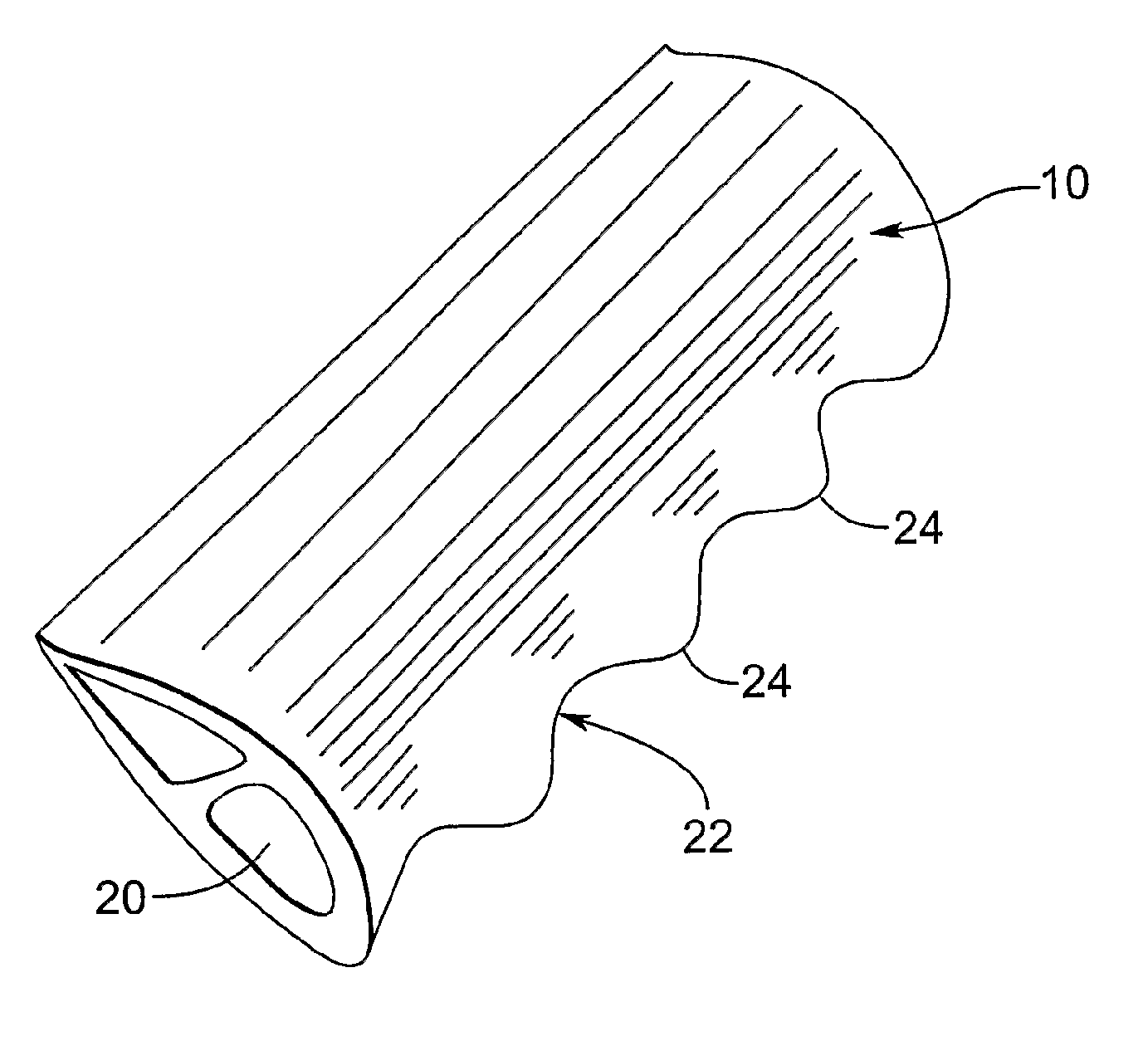
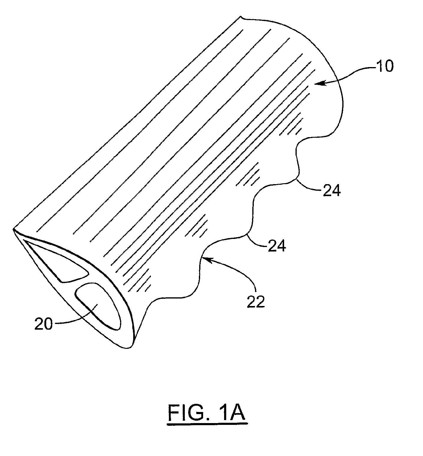
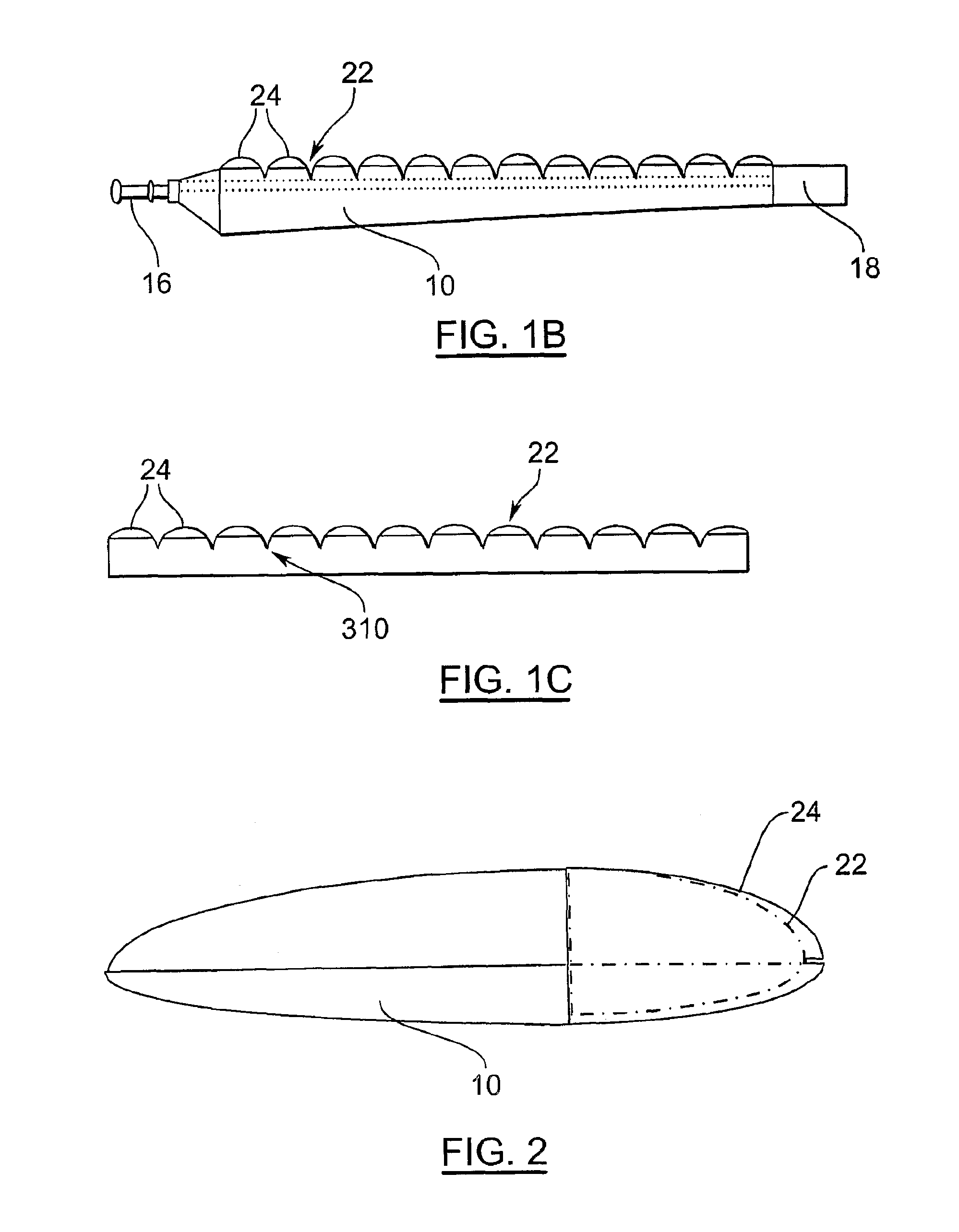
[0031]Turning now to FIGS. 1A, 1B and 2, a turbine rotor blade is shown and is generally identified by reference numeral 10. As can be seen, the turbine rotor blade 10 is coupled to a fixed hub 12 (see FIG. 3A) and has a blade body 14 extending from a root 16 to a blade tip 18. A structural beam such as a D-spar 20 is integrally formed within the blade body 14 allowing rotational power to be transmitted to the hub 12. The blade body 14 has a leading edge 22.

[0032]Unlike conventional turbine rotor blades, the leading edge 22 is provided with tubercles 24 along its length between the root 16 and the blade tip 18 similar to those described in U.S. Pat. No. 6,431,498, the content of which is incorporated herein by reference. The tubercles 24 in this case are generally evenly spaced along the leading edge 22 and provide the rotor blade 10 with enhanced lift and better stall characteristics while at the same time, reducing the drag that the rotor blade 10 exhibits.

[0033]Although not illus...


PUM


Abstract

A turbine / compressor comprises at least one magneto-electric device and a drive train coupled to the magneto-electric device. At least one rotor blade is coupled to the drive train. The rotor blade has a shaped leading edge with a series of spaced tubercles formed therealong.

Description

FIELD OF THE INVENTION[0001]The present invention relates generally to the effective capture of force from wind and other moving fluids including but not limited to water and steam and the conversion of that force into the generation of electrical power, or other usable forms of energy. More particularly, the present invention relates to a novel turbine and compressor employing a tubercle leading edge rotor design configured to enhance lift and reduce drag.BACKGROUND OF THE INVENTION[0002]Windmills and water mills have been used for centuries to pump water or to power a wide range of mechanical devices. Over the past century both have become important means of electrical power generation.[0003]In recent years there has been considerable effort expended to improve the efficiency of wind and water turbines used for electrical power generation with a view to reducing dependence on non-renewable resources. Significant expansion of the power generating capacity of such wind and water tur...

Claims


Application Information

Patent Timeline
Patent Type & Authority Patents(United States)
IPC IPC(8): F03D11/00
CPCF03B3/12F03D1/0608H02K7/183F05B2240/30F05B2240/31F05B2240/97F05B2250/61F05B2260/70F05B2260/74Y02E10/223Y02E10/721Y02E10/725Y02E10/20Y02E10/72F03D1/0633F05B2240/303
Inventor DEWAR, STEPHEN W.WATTS, PHILLIPFISH, FRANK ELIOT
Owner WHALE POWER CORP
Learn More