Alkyne-assisted nanostructure growth

a technology of nanostructures and alkyne, applied in the field of nanostructures, can solve the problems of affecting and many known methods of large-volume cnt production, including catalytic chemical vapor deposition (cvd), and posing threats to the quality of air, water and soil

Inactive Publication Date: 2013-10-01
WOODS HOLE OCEANOGRAPHIC INSTITUTION +2
View PDF6 Cites 4 Cited by
  • Summary
  • Abstract
  • Description
  • Claims
  • Application Information

AI Technical Summary

Problems solved by technology

Many known methods for large-volume CNT production, including catalytic chemical vapor deposition (CVD), are plagued by inefficiency where no more than about 3% of the introduced carbon feedstock is converted to CNT.
Recent studies have demonstrated that the effluent from an ethene-based CVD growth, i.e., by thermal treatment of common CNT feedstock gasses (C2H4 / H2), contained several compounds that pose threats to the quality of the air, water and soil.

Method used


Image

  • Alkyne-assisted nanostructure growth
  • Alkyne-assisted nanostructure growth
  • Alkyne-assisted nanostructure growth

Examples


example 1

[0077]The following example describes the identification of thermally generated CNT precursor molecules. FIG. 6B shows a schematic diagram of an atmospheric-pressure, cold-wall CVD reactor with decoupled thermal control over feedstock and catalyst. Throughout this study, feedstock gases were delivered in one of two modes: (1) with thermal treatment (Tp=680-1040° C., C2H4 and H2 only) or (2) without thermal treatment (C2H4 and H2 and a test gas, “X”). The catalyst substrate temperature (Ts) was 725° C., unless otherwise noted. The height of the growing CNT forest was monitored with a laser displacement sensor. Using the CVD reactor shown in FIG. 6B, the temperatures of the feedstock and catalyst were independently controlled. The C2H4 / H2 growth mixture was heated to various “pre-heat” temperatures, Tp (860-1040° C.), and then cooled to room temperature prior to impingement on a substrate-affixed, locally-heated metal catalyst (1 nm Fe / 10 nm Al2O3 / 675 um Si). Simultaneously, the compo...

example 2

[0080]The following example describes a general procedure for CNT synthesis. In order to measure in situ VA-MWCNT height during the reaction progress, a custom-built CVD reactor was used with a laser displacement sensor mounted above the growth chamber, as shown by the schematic diagram in FIG. 6A. Traditional growth feedstock gases (C2H4 / H2) and annealing gases (He / H2) are introduced via a resistively heated pre-heater tube that was operated in two modes: (1) “on” at 1000° C. and (2) “off” at room temperature (21° C.). With the pre-heater off, test gases (e.g., 1,3-butadiene, acetylene, methyl acetylene, 1-butyne, vinyl acetylene, methane, ethane, or benzene) were introduced during the growth phase via a secondary input line, which could be flushed to a vent via a 3-way valve during the flush and anneal phases. The flow rate of the test gas was balanced with an additional helium line that was cryogenically purified with a Porasil-C column immersed in liquid nitrogen. For all experi...

example 3

Accelerated CNT Growth without Heating Feedstock Gases

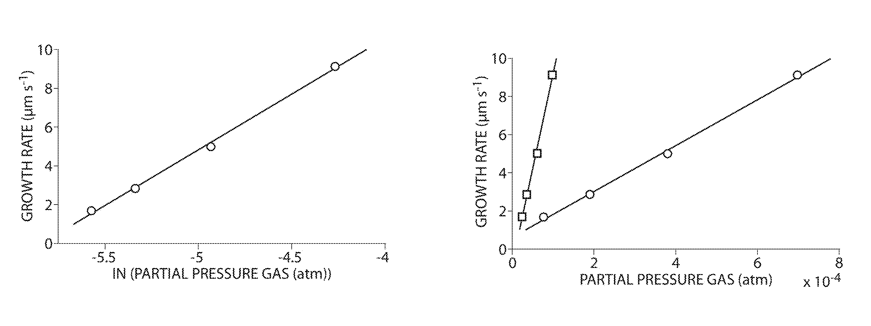
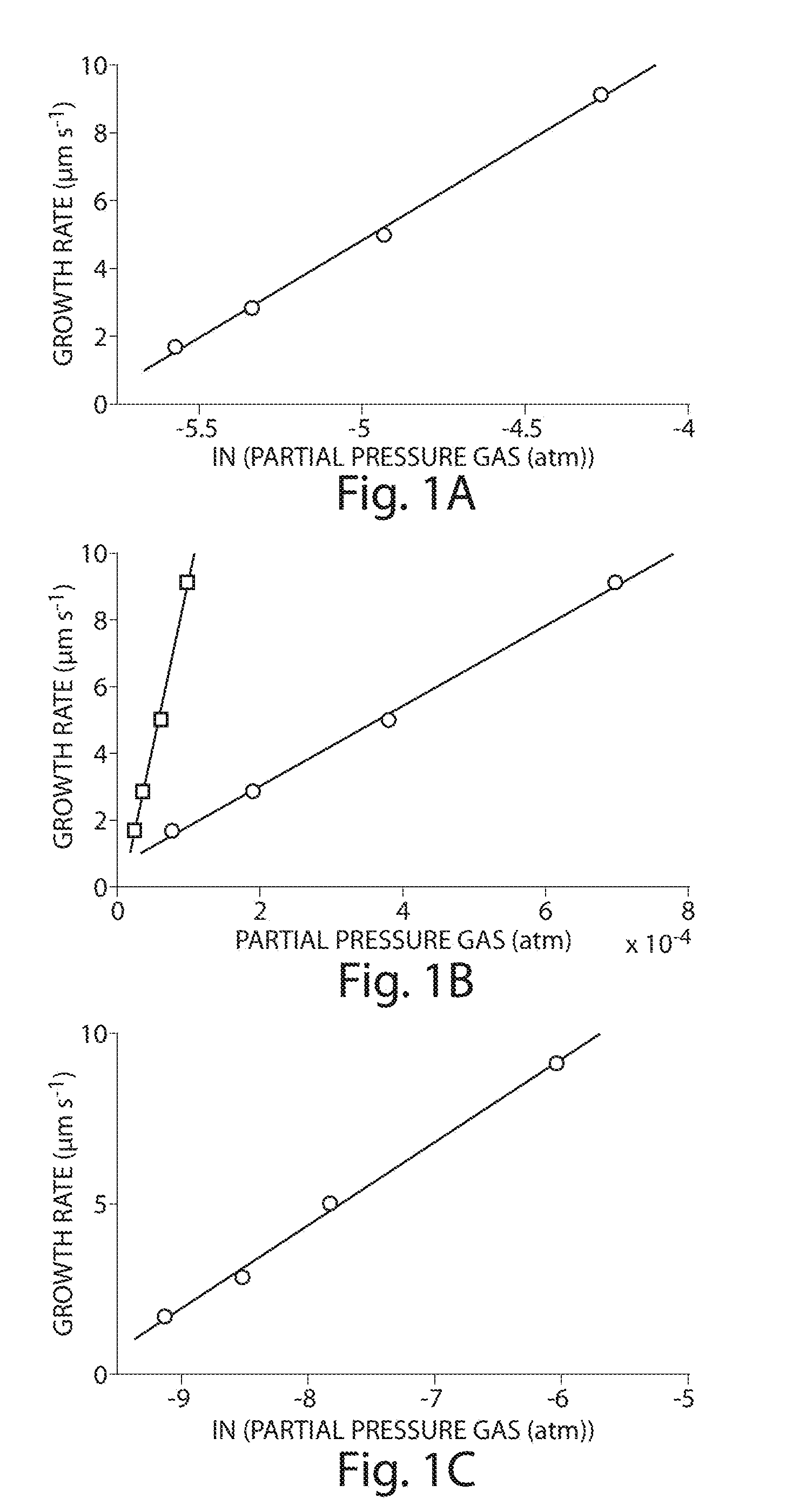
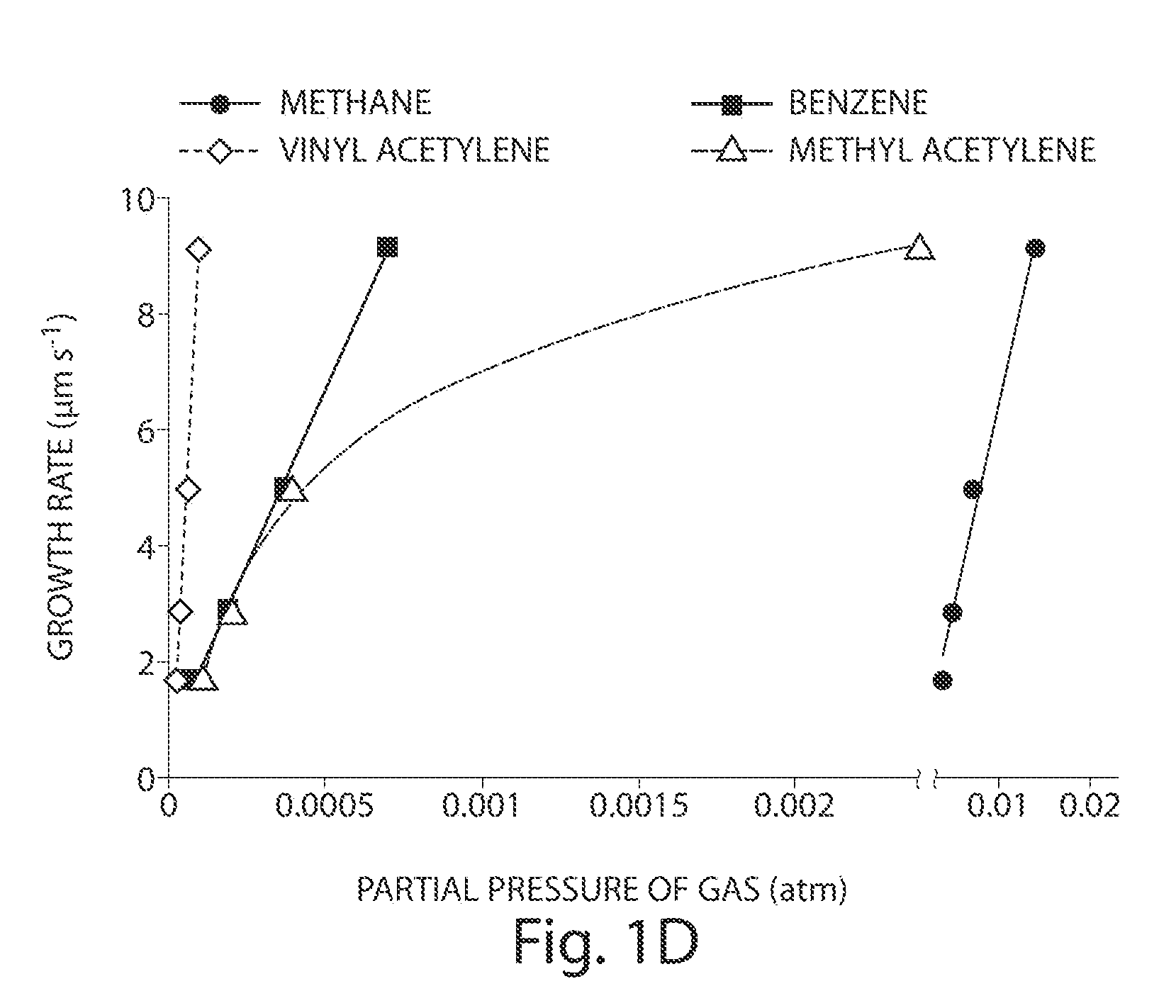
[0083]Using a decoupled CVD reactor, the temperature of VA-MWCNT metal catalyst and C2H4 / H2 feedstock was independently controlled while monitoring the composition of gases evolved from the pre-heater, as well as the in situ VA-MWCNT forest growth rate. As the pre-heater temperature increased (from 690 to 1200° C.), the growth rate of the VA-MWCNT forest increased. FIG. 1 shows various graphs illustrating the correlation between thermally generated compounds and increases in VA-MWCNT growth rate. In all subplots, the symbols are measured data and the line is the best-fit curve. FIG. 1A shows methane's abundance was equally well fit by linear and logarithmic relationship with the growth rate (R2=0.99, n=4). FIG. 1B shows that benzene (circles) and vinyl acetylene (squares) were linearly related to the growth rate (R2=0.99, n=4). FIG. 1C shows that methyl acetylene is logarithmically related to the VA-MWCNT growth rate (R2=0.99, n=...


PUM

PropertyMeasurementUnit
temperatureaaaaaaaaaa

Abstract

The present invention relates to the formation and processing of nanostructures including nanotubes. Some embodiments provide processes for nanostructure growth using relatively mild conditions (e.g., low temperatures). In some cases, methods of the invention may improve the efficiency (e.g., catalyst efficiency) of nanostructure formation and may reduce the production of undesired byproducts during nanostructure formation, including volatile organic compounds and / or polycylic aromatic hydrocarbons. Such methods can both reduce the costs associated with nanostructure formation, as well as reduce the harmful effects of nanostructure fabrication on environmental and public health and safety.

Description

RELATED APPLICATIONSUtility[0001]This application claims priority under 35 U.S.C. §119(e) to co-pending U.S. Provisional Application Ser. No. 61 / 187,704, filed Jun. 17, 2009, the contents of which are incorporated herein by reference in its entirety.STATEMENT REGARDING FEDERALLY SPONSORED RESEARCH OR DEVELOPMENT[0002]This invention was made with the support under the following government contract: CMMI0800213 awarded by the National Science Foundation. The government has certain rights in the invention.FIELD OF THE INVENTION[0003]The present invention relates to nanostructures, and related methods.BACKGROUND OF THE INVENTION[0004]The industrial and laboratory-scale production of carbon nanotubes (CNTs) has been increasing for the last decade, with current production volumes at 1,300 tons year−1 globally (ton=106 g) (e.g., with a doubling rate of once every two years and assuming that the CNT mass:US $ ratio is unchanged over the next ten years). Many known methods for large-volume C...

Claims


Application Information

Patent Timeline
Patent Type & Authority Patents(United States)
IPC IPC(8): D01C5/00
CPCB82Y30/00B82Y40/00C01B31/0226C01B31/0293C01B32/16C01B32/18
Inventor PLATA, DESIREE L.GSCHWEND, PHILIP S.HART, ANASTASIOS JOHNMESHOT, ERIC R.REDDY, CHRISTOPHER M.
Owner WOODS HOLE OCEANOGRAPHIC INSTITUTION
Why Eureka
Try Eureka