Marine propulsion device

a propulsion device and thruster technology, applied in the direction of hybrid vehicles, vessel auxillary drives, vessel construction, etc., can solve the problems of reducing efficiency, unfavorable fuel cost and maintenance, and increasing the emission of greenhouse gas, so as to reduce manufacturing costs, facilitate assembly to the ship, and simple and compact configuration

Active Publication Date: 2013-10-15
IHI POWER SYST CO LTD
View PDF21 Cites 10 Cited by
  • Summary
  • Abstract
  • Description
  • Claims
  • Application Information

AI Technical Summary

Benefits of technology

[0023]According to the marine propulsion device as described in claim 1, the so-called azimuth thruster adapted to set the propulsion direction by revolving the horizontal propeller shaft around the vertical shaft for transmitting the power adopts the structure in which the main engine is connected only to one end side of the input / output shaft of the azimuth thruster through the single power transmission clutch without interposing a complicated speed reducing mechanism, and the motor generator is direct-coupled to the other end side. Therefore, a simple and compact-sized configuration can be realized and assembling to the ship can be facilitated to reduce the manufacturing cost. Furthermore, even when one of the main engine and the motor generator is broken, the operation can be performed without a hindrance, and the clutch is only one power transmission clutch, being simple without a speed reducer, so that the reliability as the marine propulsion device is high. Furthermore, since adopted is a hybrid system in which a power source as the propulsion device is combination of the main engine and the motor generator, the efficient drive control fit for the load state of the ship can be realized to reduce fuel consumption, lower the output of the main engine and enable downsizing. With this advantage, the running cost and the greenhouse gas emission amount can be reduced, and in addition, the degree of freedom in layout can be heightened by downsizing.
[0024]According to the marine propulsion device as described in claim 2, the motor generator is fixed directly to the base part, which is mounted at the bottom of the ship and to which the horizontal input / output shaft is fitted, and the motor generator is direct-coupled to the other end side of the input / output shaft, so that the configuration as the whole device is further compact-sized. Furthermore, in performing the operation for installing the marine propulsion device in the ship in a shipyard, it will suffice to mount the base part at the bottom of the ship and connect the main engine of the ship to the driving force transmission clutch, so the operation is simple. That is, apart from the operation for mounting the base part at the bottom of the ship, it is not necessary to mount the motor generator at a required position of the bottom of the ship or again connect the same to the input / output shaft on the base part, and therefore the man-hour can be decreased to realize further reduction in manufacturing cost.
[0025]According to the marine propulsion device as described in claim 3, in the motor propulsion, the slip control conducted in the low-speed drive state of the main engine is not needed, so that generation of heat and power loss in the power transmission clutch caused by the slip control can be reduced. Further, in the case of stopping the main engine in the motor propulsion, the running cost and the greenhouse gas emission amount during that engine stop can be decreased. The motor generator sharing the load with the main engine may drive just for its share of the output, so the motor generator can be miniaturized to be carried integral on the base part of the azimuth thruster without a hindrance. The operation in the low load region of the main engine is decreased, and the operation in the efficient load region is possible so that fuel consumption is improved. In the motor propulsion, since the motor generator is driven as the motor, the torque can be 100% output even in the low rotation state to quickly respond to the propeller load and facilitate fine adjustment. Thus, ship handling performance can be improved. In the hybrid propulsion, while the propeller drive having good transmission efficiency is performed by the main engine, the motor generator can be used as the motor or the generator according to the load state, so that in acceleration, torque assist can be obtained from the motor generator acting as a motor. In cruising and deceleration, the motor generator acting as a generator performs power generation to thereby charge the condensed discharge mechanism such as a battery provided at need, and surplus energy can be recovered.
[0026]According to the marine propulsion device as described in claim 4, the main engine and the two-way inverter are integrated-controlled by the controller to thereby smoothly switch between the motor generator and the main engine. In the motor propulsion, the motor generator is speed-controlled to thereby enable fine ship handling in the low speed region, and in the hybrid propulsion, while the output of the main engine is taken as base load, the controller controls the motor generator as a motor according to the ship running state, thereby assisting the main engine, or the motor generator is acted as the generator to generate power with surplus energy. Thus, efficient ship running is enabled according to the load state. In addition, since the main engine can be operated in the efficient region, fuel consumption can be reduced.
[0027]According to the marine propulsion device as described in claim 5, the power to the motor can be supplied from the generation engine and the condensed discharge mechanism, so that the capacity of the generation engine can be made smaller than the capacity of the motor generator, and compactness can be realized by downsizing. Further, the power supply is given redundancy so that even when one is broken, the operation can be performed without a hindrance.
[0028]The controller always monitors the charging depth of the condensed discharge mechanism, and when it reaches a certain charging depth or more, generation from the motor generator is paused to avoid overcharge.

Problems solved by technology

In a work barge such as a tugboat, since a main engine is selected according to the output required in work, the load factor of the main engine is lowered in the moving or standby state except the working state, and this is unfavorable in the fuel cost and the maintenance and management.
Consequently, output loss and heating loss due to a slip occur to lower the efficiency, and further the emission amount of greenhouse gas is larger as compared with the obtained output.
On the other hand, in the variable speed control by electric propulsion which has been increasing in recent years, the slip control in the low speed moving state is not required, but the work barge such as a tugboat requires great output in work, so that when transmission loss due to electric propulsion is taken into consideration, the required capacity of a power generation engine and output of the motor are increased, resulting in the problem of difficulty in casing the engine and the motor in the present ship form.

Method used


Image

  • Marine propulsion device
  • Marine propulsion device
  • Marine propulsion device

Examples


first embodiment

1. First Embodiment

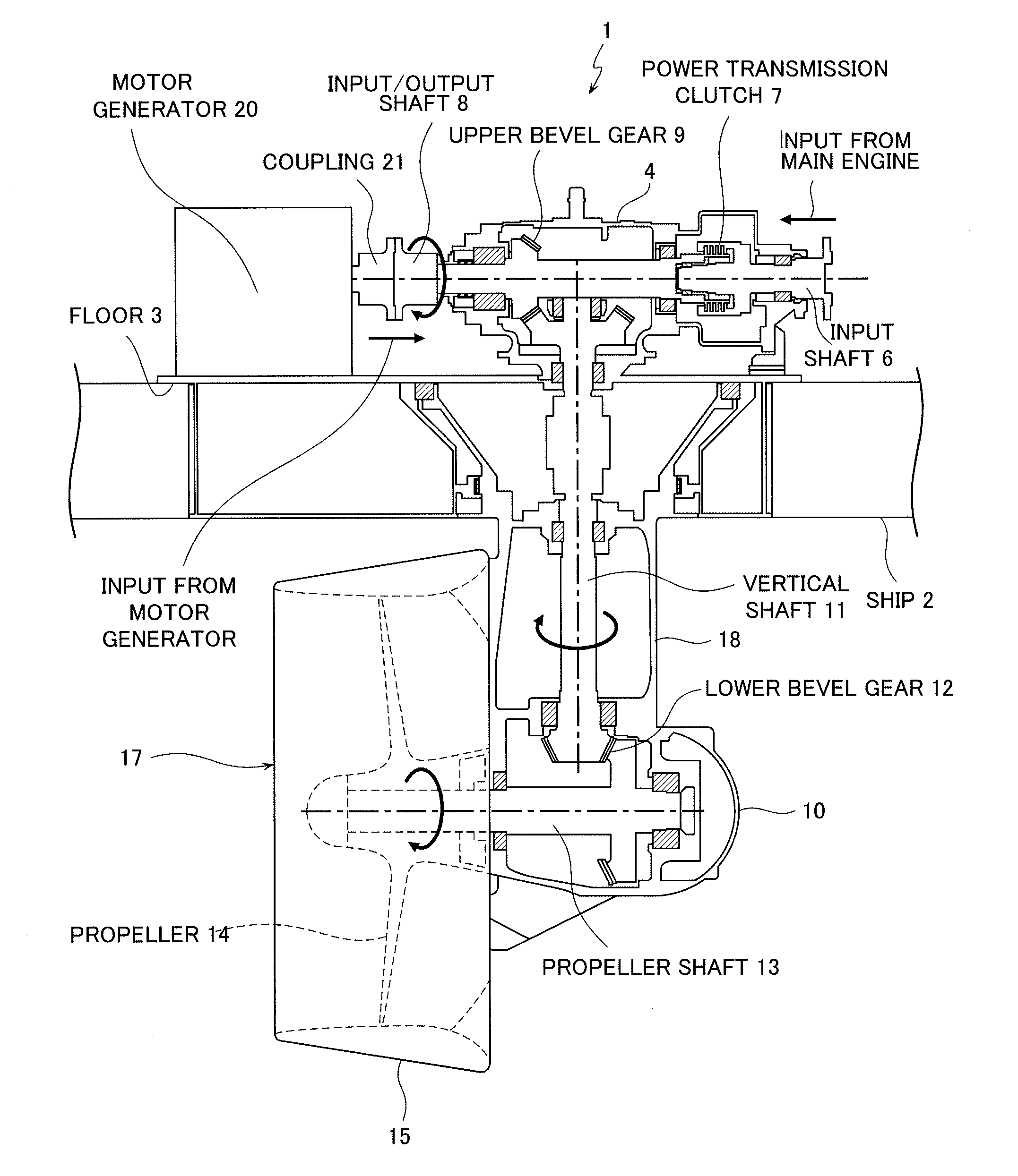
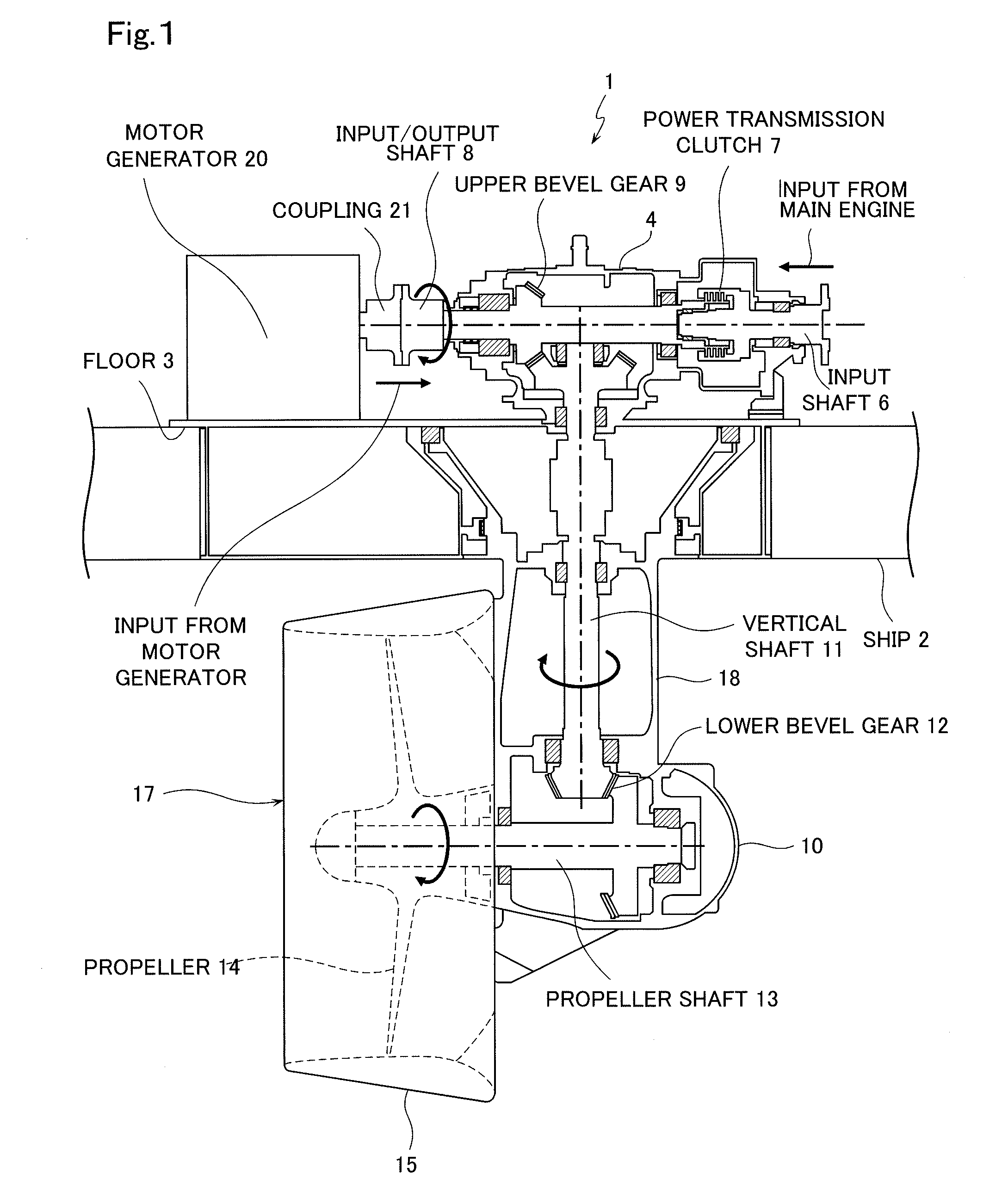
[0044]A marine propulsion device according to a first embodiment is an azimuth thruster adapted to set the propulsion direction by revolving a horizontal propeller shaft around a vertical shaft for transmitting power, which particularly enables propulsion with a motor generator simplex, propulsion with a main engine simplex, and hybrid propulsion in which assist of the motor generator is given to the output of the main engine by connecting a main engine and a motor generator to both ends of a horizontal input / output shaft of the azimuth thruster, respectively.

(1) Configuration (FIG. 1 and FIG. 2)

[0045]As shown in FIG. 1, in the stern of a ship 2 carrying the marine propulsion device 1 of the embodiment, a floor 3 serving as a base part of an azimuth thruster 17 of the marine propulsion device 1 is fixed at the bottom thereof. A gear case 4 is mounted on the top surface side of the floor 3, and a horizontal input shaft 6 connected to a main engine 5 shown in FIG. 2...

second embodiment

2. Second Embodiment

FIG. 10 and FIG. 11

[0084]A second embodiment relates to a ship 2 including a marine propulsion device 1 similar to the first embodiment and further carrying a fire pump. In the description of the present embodiment, concerning the same or like parts as those of the first embodiment, the description in the first embodiment is quoted to suitably eliminate the description by using the same reference signs as those in the drawings of the first embodiment.

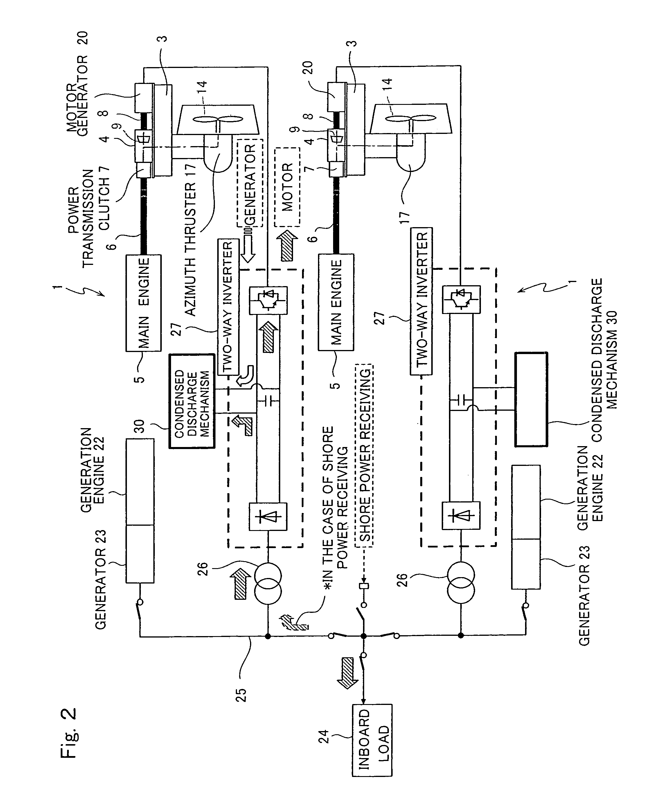
[0085]As shown in FIG. 10, in the marine propulsion device 1 mounted on the ship 2 according to the present embodiment, the main engine 5 is connected to one end side of the horizontal input / output shaft 8 of the azimuth thruster 17 (an azimuth thruster for a hybrid propulsion system) through the power transmission clutch 7, and the motor generator 20 is connected to the other end side of the input / output shaft 8. The propeller 14 is a fixed pitch propeller, which is simple in structure and inexpensive. A rear end si...

third embodiment

3. Third Embodiment

FIG. 14

[0091]FIG. 14 is a control system diagram of a marine propulsion device 1′ according to a third embodiment, which improves the first embodiment shown in FIG. 9, and provides a system adapted to input the revolution number information of the motor generator 20 from the two-way inverter 27 to a controller 40′. The substantially same components as those of the first embodiment are designated by the same reference signs as those of FIG. 9 in FIG. 14 to eliminate the description.

[0092]In the present embodiment, the controller 40′, which controls the main engine 5 and the two-way inverter 27, always acquires information of the number of revolutions of the main engine 5 and the number of revolutions of the motor generator 20. In switching from a motor propulsion region to a hybrid region at a switching predetermined number of revolutions, the controller outputs a clutch control signal for putting a clutch in the on state after confirming that both numbers of revol...


PUM


Abstract

In a hybrid type marine propulsion device including a main engine and a motor, low fuel consumption is realized by a compact configuration and highly efficient drive control.A marine propulsion device includes a clutch 7 provided on an input shaft 6 of a main engine, a horizontal input / output shaft 8 connected to the clutch, a vertical shaft 11 connected to the input / output shaft through an upper bevel gear 9, a horizontal propeller shaft 13 connected to a lower end of the vertical shaft through a lower bevel gear 12, and a propeller 14 at the other end side of the propeller shaft, in which the propeller is revolved around the vertical shaft to set a propulsion direction, wherein a motor generator 20 is mounted on a floor 3, and connected directly to the other end side of the input / output shaft. In a low rotation region, motor propulsion is performed, and in a high rotation region, hybrid propulsion in which the main engine is assisted by the motor is performed.

Description

RELATED APPLICATIONS[0001]The present application is National Phase of International Application No. PCT / JP2010 / 064651 filed Aug. 20, 2010, and claims priority from Japanese Application No. 2009-192186, filed Aug. 21, 2009 and No. 2009-241619, filed Oct. 20, 2009.TECHNICAL FIELD[0002]This invention relates to the so-called azimuth thruster, which sets the propulsion direction by revolving a horizontal propeller shaft around a vertical shaft for transmitting power and particularly to a marine propulsion device which enables propulsion in a motor generator simplex, propulsion in a main engine simplex, and hybrid propulsion in which the assist of the motor generator is added to the output of the main engine.BACKGROUND ART[0003]In a work barge such as a tugboat, since a main engine is selected according to the output required in work, the load factor of the main engine is lowered in the moving or standby state except the working state, and this is unfavorable in the fuel cost and the ma...

Claims


Application Information

Patent Timeline
Patent Type & Authority Patents(United States)
IPC IPC(8): B63H21/20B60L50/15B60L50/16
CPCB63H5/1252B63H21/21B63H23/30B63J3/02B60L11/126B60L11/14Y02T10/6217B60L2200/32Y02T10/7077Y02T70/5236B63H5/125B60L50/62B60L50/16Y02T10/62Y02T10/7072Y02T10/70
Inventor KODERA, MASANORINANKE, YOSHIKISHIRAISHI, KOICHIAIZAWA, YASUOSAITO, TOSHIYUKI
Owner IHI POWER SYST CO LTD
Why Eureka
Try Eureka