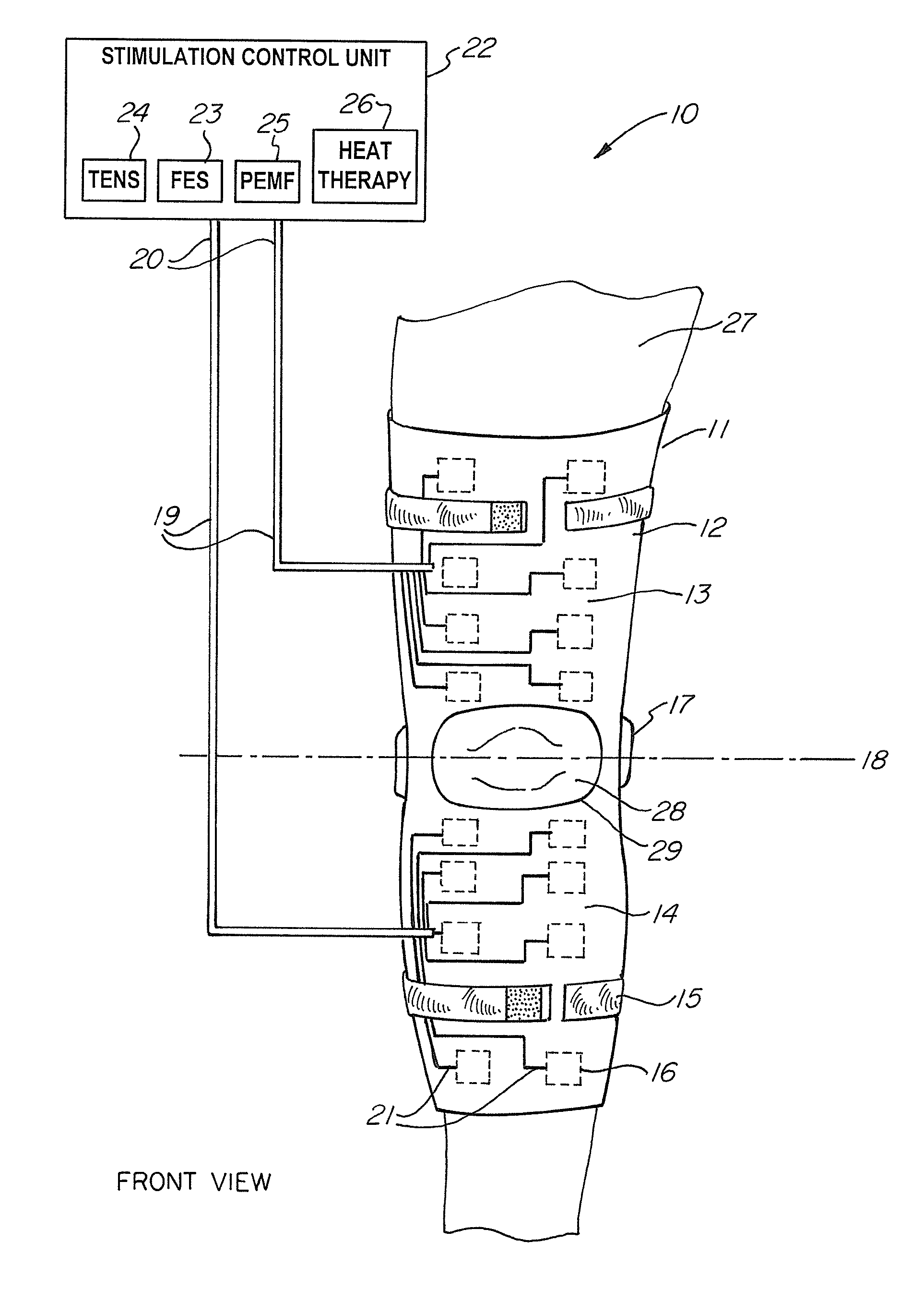
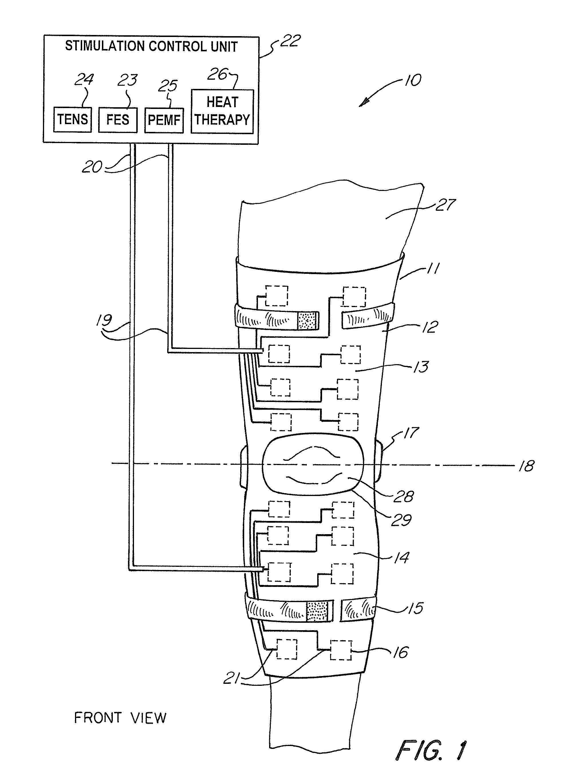
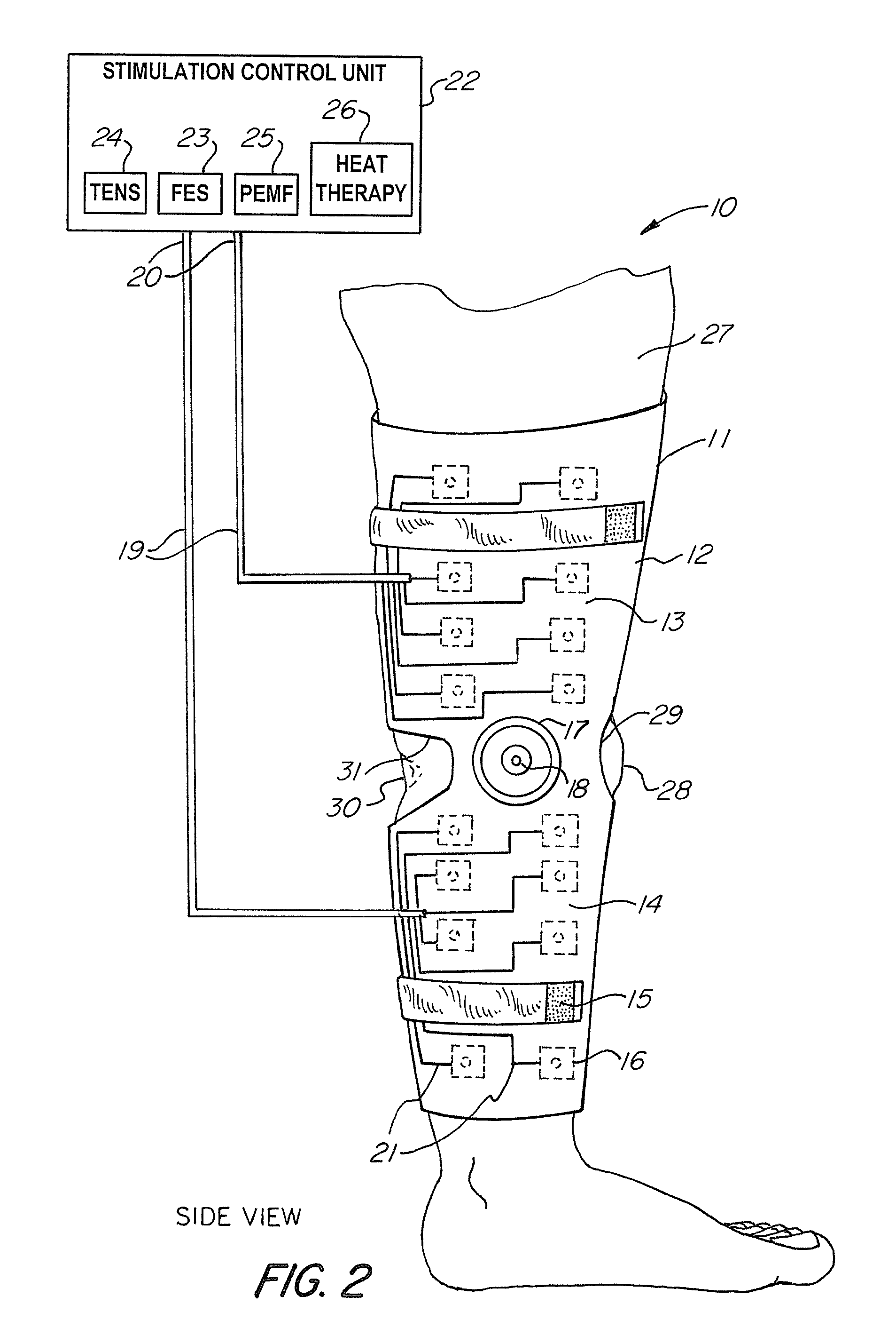
Universal musculoskeletal rehab device (brace, sleeve, or pad) for electrical treatment modalities and biofeedback response monitoring
a rehabilitation device and musculoskeletal technology, applied in the field of rehabilitation devices, can solve the problems of reducing the rehabilitative effect of certain joints, affecting the function of certain joints, and reducing the rehabilitative effect of certain limbs and spines
- Summary
- Abstract
- Description
- Claims
- Application Information
AI Technical Summary
Benefits of technology
Problems solved by technology
Method used
Image
Examples
second embodiment
[0053]FIG. 4B shows a block diagram of the stimulation control unit according to the present invention. In this embodiment, the stimulation control unit 22 comprises a power source 34, a microcontroller 35, an input unit 36, a monitor 37, and a transmitter-receiver unit 40. Further, each of the electrodes 16 comprises a transmitter-receiver unit 40. The transmitter-receiver units 40 establish wireless communication between the stimulation control unit 22 and the electrodes 16, thus providing control of the electrodes 16. The transmitter-receiver units 40 also communicate muscle responses and nerve activity from the electrodes 16 to the neuromuscular feedback component 38 and neurofeedback mechanism 39, respectively. Biomechanical response and range of motion data is also sent back wirelessly from the electrodes 16 to the biomechanical component 46.
[0054]FIG. 5A is a front view of the stimulation control unit 22 as embodied in FIG. 4A. Using the input unit 36, the user can program a ...
third embodiment
[0061]Referring to FIG. 10, there is shown the non-invasive, orthotic device according to the present invention. FIG. 10, in particular, shows an orthotic device 70 having a brace 71, a pair of brace hinges 73 disposed on the brace 71, a sleeve 75, electrodes 78, conductors 79, and a stimulation control unit 80 for establishing a controlled sequence of transmission of electrophysical modalities. The electrodes 78 are removably attached to an inner lining of the sleeve 75 such that the electrodes 78 are in direct contact with the user's leg 85. The sleeve 75 further comprises sleeve fasteners 76 disposed on the outer lining of the sleeve 75 (also shown as 63 in FIG. 9). The sleeve fasteners 76 are adapted to releasably engage the inner surface (not shown) of the brace 71 when the user positions his leg 85 into the brace 71. Once the user is wearing the brace 71, the sleeve fasteners 76 provide a secure attachment between the sleeve 75 and the brace 71 preventing any slipping motion b...
fourth embodiment
[0063]Referring to FIG. 11, the non-invasive, orthotic device is shown. FIG. 11 illustrates an orthotic device 100 comprising a flexible pad 101, a plurality of electrodes 102 disposed on the flexible pad 101, a stimulation control unit 104, and one or more conductors 103 each having a proximal end connected to the stimulation control unit 104 and a distal end connected to one or more electrodes 102. The flexible pad 101 is made of any material having flexible and elastic characteristics, such as fabric, plastic, or latex rubber, which allows it to conform to any anatomical aspects of the user's leg 110, knee 111, or other body part. In one embodiment, the flexible pad 101 also has an adhesive portion disposed on an inner lining (not shown) of the flexible pad 101 and adapted to removably attach to any part of the user's leg 110. As one example, the adhesive portion comprises a pressure-sensitive adhesive composition. In another example, the adhesive portion can be composed of medic...
PUM
 Abstract
Description
Claims
Application Information
 - R&D
- Intellectual Property
- Life Sciences
- Materials
- Tech Scout
- Unparalleled Data Quality
- Higher Quality Content
- 60% Fewer Hallucinations
Browse by: Latest US Patents, China's latest patents, Technical Efficacy Thesaurus, Application Domain, Technology Topic, Popular Technical Reports.
© 2025 PatSnap. All rights reserved.Legal|Privacy policy|Modern Slavery Act Transparency Statement|Sitemap|About US| Contact US: help@patsnap.com


