Micro gap flow through electrochemical devices with self adjusting reactive surfaces

a technology of reactive surface and micro gap flow, which is applied in the direction of electrical equipment, metal-working equipment, electrochemical devices, etc., can solve the problems of increasing the size of the electrode, and reducing the return

Inactive Publication Date: 2013-11-12
CLARKE RICHARD
View PDF4 Cites 20 Cited by
  • Summary
  • Abstract
  • Description
  • Claims
  • Application Information

AI Technical Summary

Problems solved by technology

However, numerous difficulties still remain.
Among other things, diminishing returns will arise as reactant concentrations decline, and increasing the size of the electrodes will fairly quickly reach practical limitations.
However, when cell gaps are less than 1 mm the model fails as the boundary layers collapse on each other and flow equivalent to a gravity fed cell with only tens of cm of head would produce a well mixed thin boundary layer surface by laminar flow alone.
This artificial mathematical modeling often works fairly well in certain systems, but fails as the size of the gap between the walls of the system, d, becomes very small as turbulent flow is restricted and laminar flow is predominant.
Therefore, while numerous configurations and methods of electrochemical devices are known in the art, all or almost all of them suffer from one or more disadvantages, especially where the cell gap is relatively small.

Method used


Image

  • Micro gap flow through electrochemical devices with self adjusting reactive surfaces
  • Micro gap flow through electrochemical devices with self adjusting reactive surfaces
  • Micro gap flow through electrochemical devices with self adjusting reactive surfaces

Examples


Embodiment Construction

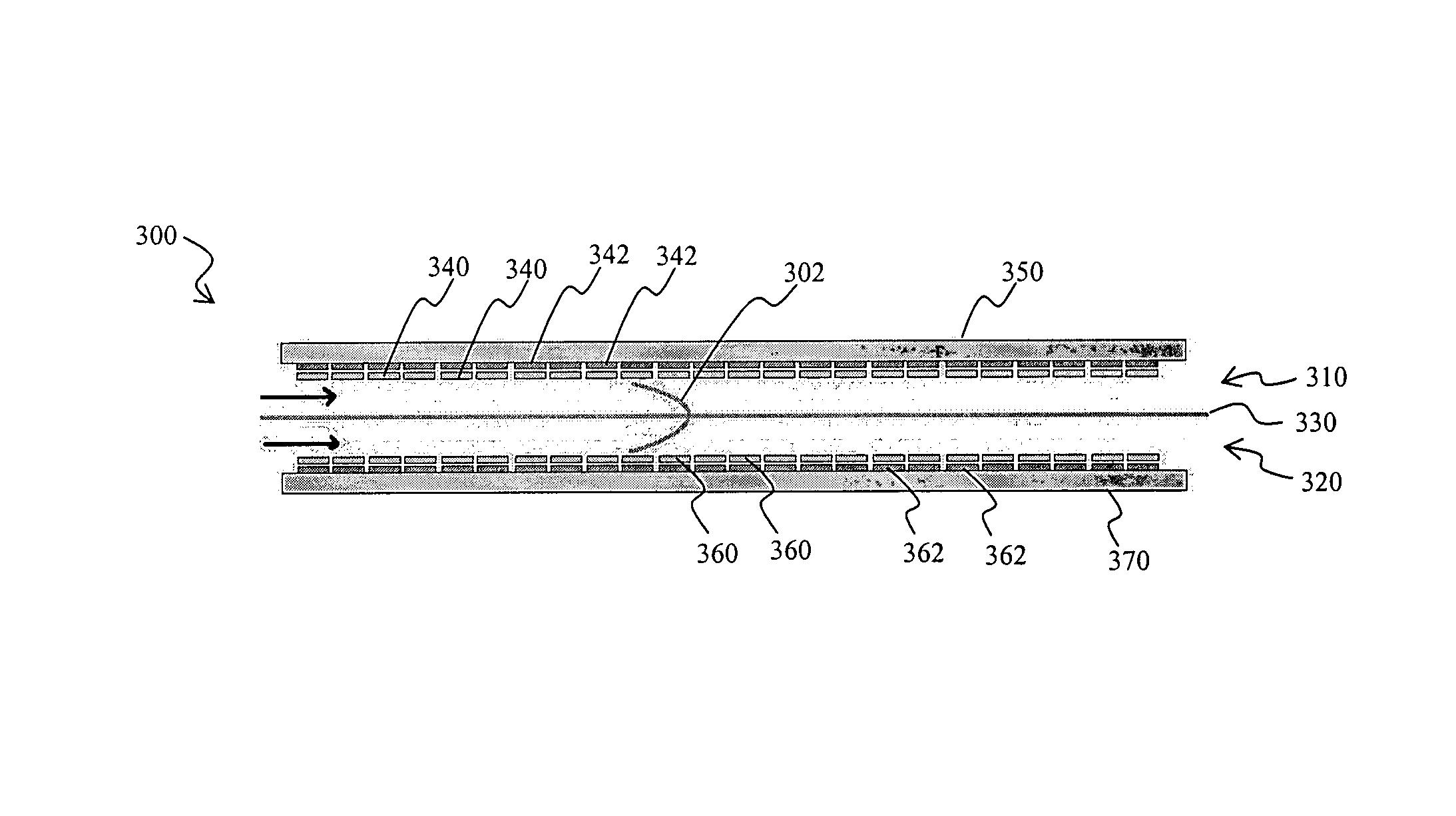
[0023]The inventor has discovered that numerous electrochemical devices can be configured in a simple and effective manner in which heretofore known problems associated with mass transport phenomena are substantially eliminated. Contemplated devices and methods will provide substantially improved reaction kinetics and “good-to-the-last-drop” performance of power cells.

[0024]Therefore, in one aspect of the inventive subject matter, electrochemical reactors use highly restricted electrolyte pathways in which the boundary layers of laminar flow at the electrode walls begin to touch each other and allow for perfect mixing in a single boundary layer at laminar flow. Viewed from a different perspective, configurations and methods are contemplated in which electrolyte films move through an electrochemical reactor. Therefore, and among other configurations, a one pass reactor is particularly contemplated in which the rate of reaction and completion of reaction are controlled by the electrol...


PUM

PropertyMeasurementUnit
Reynolds numbersaaaaaaaaaa

Abstract

Contemplated electrochemical devices and methods include an electrolyte flow path in which substantially all of the electrolyte has laminar flow. A segmented electrode contacts the electrolyte, and each of the segments in the segmented electrode is preferably coupled to a control device to provide control over the flow of current to and / or from the electrolyte. Thus, it should be appreciated that the redox state of the electrolyte can be changed in a single-pass through the flow path, which effectively eliminates problems associated with mass transport phenomena and reduced current efficiency.

Description

[0001]This application claims priority to our U.S. provisional patent application with the Ser. No. 60 / 859,036, filed Nov. 14, 2006, and which is incorporated by reference herein.FIELD OF THE INVENTION[0002]The field of the invention is electrochemical devices and methods therefor.BACKGROUND OF THE INVENTION[0003]Numerous electrochemical processes are widely used, and examples include electric storage batteries, production of basic raw materials (e.g., aluminum, chlorine, caustic soda, titanium, hydrogen, etc.). More recently, electrochemical devices are also used in medical devices to monitor blood sugar, drugs, or help analyze DNA. Thus, and depending on the type of use, electrochemical devices may considerably vary in size and overall design.[0004]Remarkably, despite the enormous variety of electrochemical devices, the electrodes and their configurations substantially remained the same. Among other factors, the common thread in electrochemical processes and processing is that the...

Claims


Application Information

Patent Timeline
Patent Type & Authority Patents(United States)
IPC IPC(8): H01M2/38H01M8/04H01M4/36C25B9/04
CPCH01M2/38H01M8/04186H01M8/04582H01M8/04902Y02E60/50H01M50/70Y02E60/10Y10T29/49002
Inventor CLARKE, RICHARD
Owner CLARKE RICHARD
Why Eureka
Try Eureka