Electrophoretic particles and processes for the production thereof

a technology of electrophoretic particles and processes, applied in the field of electrophoretic particles, can solve the problems of inadequate service life of these displays, preventing widespread use, and gas-based electrophoretic media appearing to be susceptible to the same types of problems

Inactive Publication Date: 2013-11-12
E INK CORPORATION
View PDF72 Cites 71 Cited by
  • Summary
  • Abstract
  • Description
  • Claims
  • Application Information

AI Technical Summary

Problems solved by technology

Nevertheless, problems with the long-term image quality of these displays have prevented their widespread usage.
For example, particles that make up electrophoretic displays tend to settle, resulting in inadequate service-life for these displays.
Such gas-based electrophoretic media appear to be susceptible to the same types of problems due to particle settling as liquid-based electrophoretic media, when the media are used in an orientation which permits such settling, for example in a sign where the medium is disposed in a vertical plane.
Indeed, particle settling appears to be a more serious problem in gas-based electrophoretic media than in liquid-based ones, since the lower viscosity of gaseous suspending fluids as compared with liquid ones allows more rapid settling of the electrophoretic particles.
However, the service life of encapsulated electrophoretic displays, of both the single and dual particle types, is still lower than is altogether desirable.
In this regard, opposite charge dual particle electrophoretic displays pose a particularly difficult problem, since inherently oppositely charged particles in close proximity to one another will be electrostatically attracted to each other and will display a strong tendency to form stable aggregates.
Experimentally, it has been found that if one attempts to produce a black / white encapsulated display of this type using untreated commercially available titania and carbon black pigments, the display either does not switch at all or has a service life so short as to be undesirable for commercial purposes.
Later, it was found that simple coating of the electrophoretic particles with the modifying material was not entirely satisfactory since a change in operating conditions might cause part or all of the modifying material to leave the surface of the particles, thereby causing undesirable changes in the electrophoretic properties of the particles; the modifying material might possibly deposit on other surfaces within the electrophoretic display, which could give rise to further problems.
Furthermore, a polymer with only a few sites capable of reacting with the particle material has difficulty in reacting with the solid interface at the particle surface; this can be due to polymer chain conformation in solution, steric congestion at the particle surface, or slow reactions between the polymer and the surface.
Often, these problems restrict such reactions to short polymer chains, and such short chains typically only have a small effect on particle stability in electrophoretic media.
It has now been found that, at least with many polymeric modifying materials, this is not in fact the case, and that there is an optimum amount of polymer which should be deposited; too large a proportion of polymer in the modified particle causes an undesirable reduction in the electrophoretic mobility of the particle.

Method used

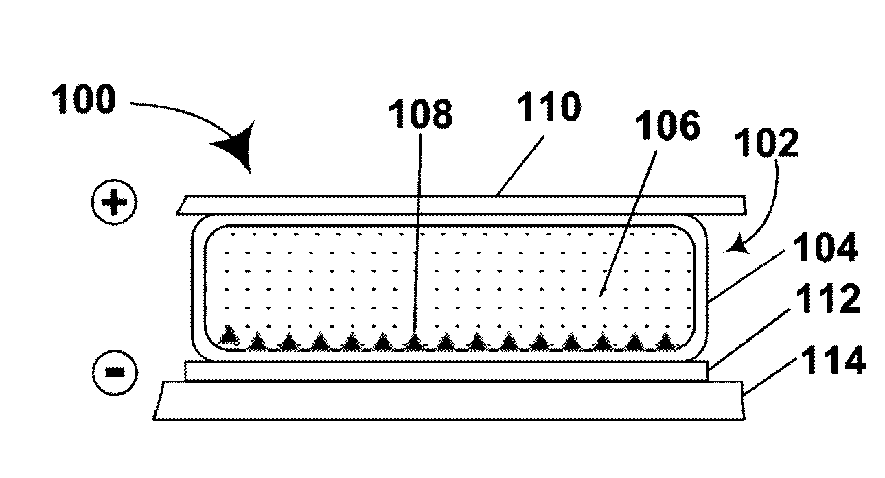
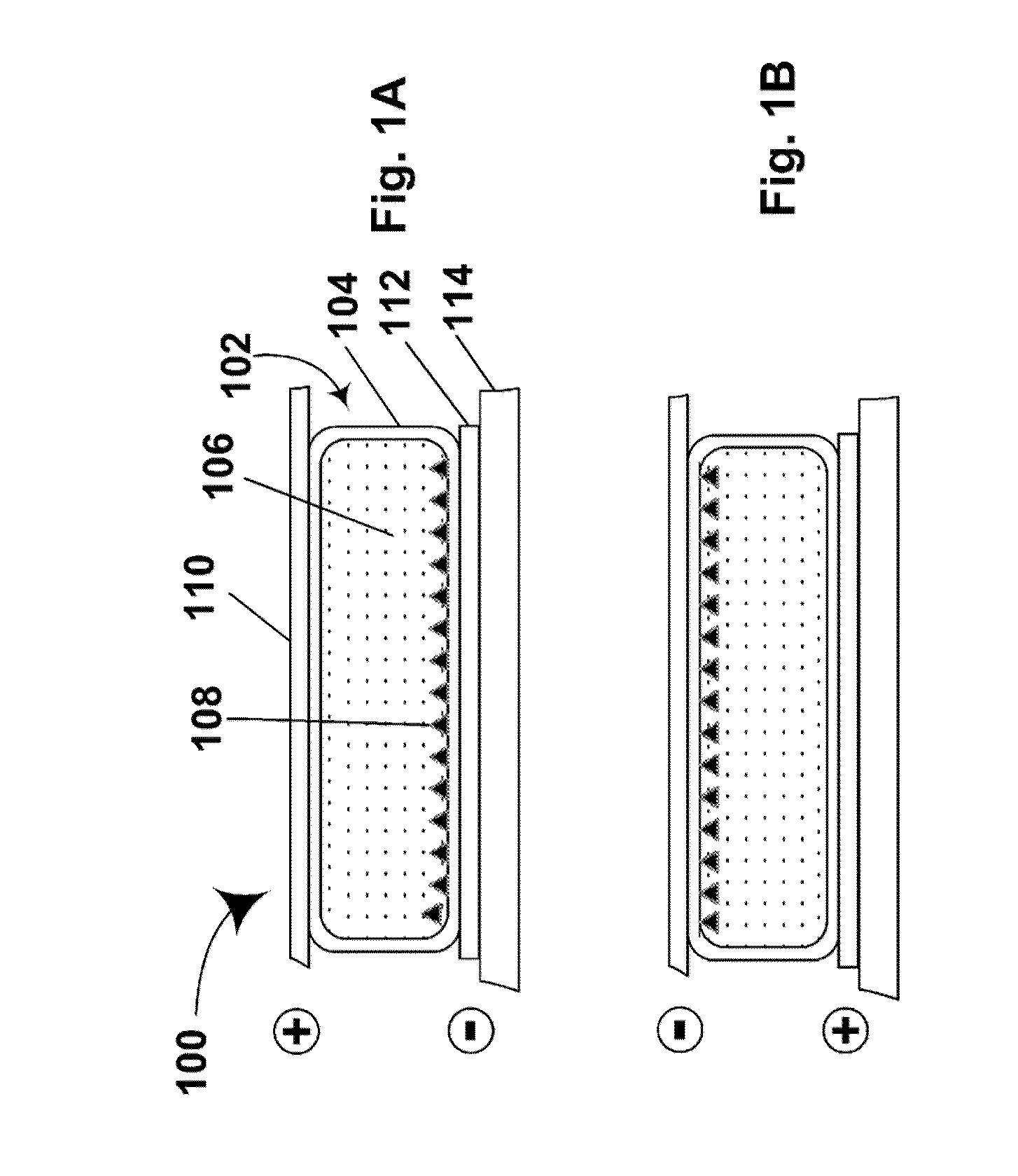
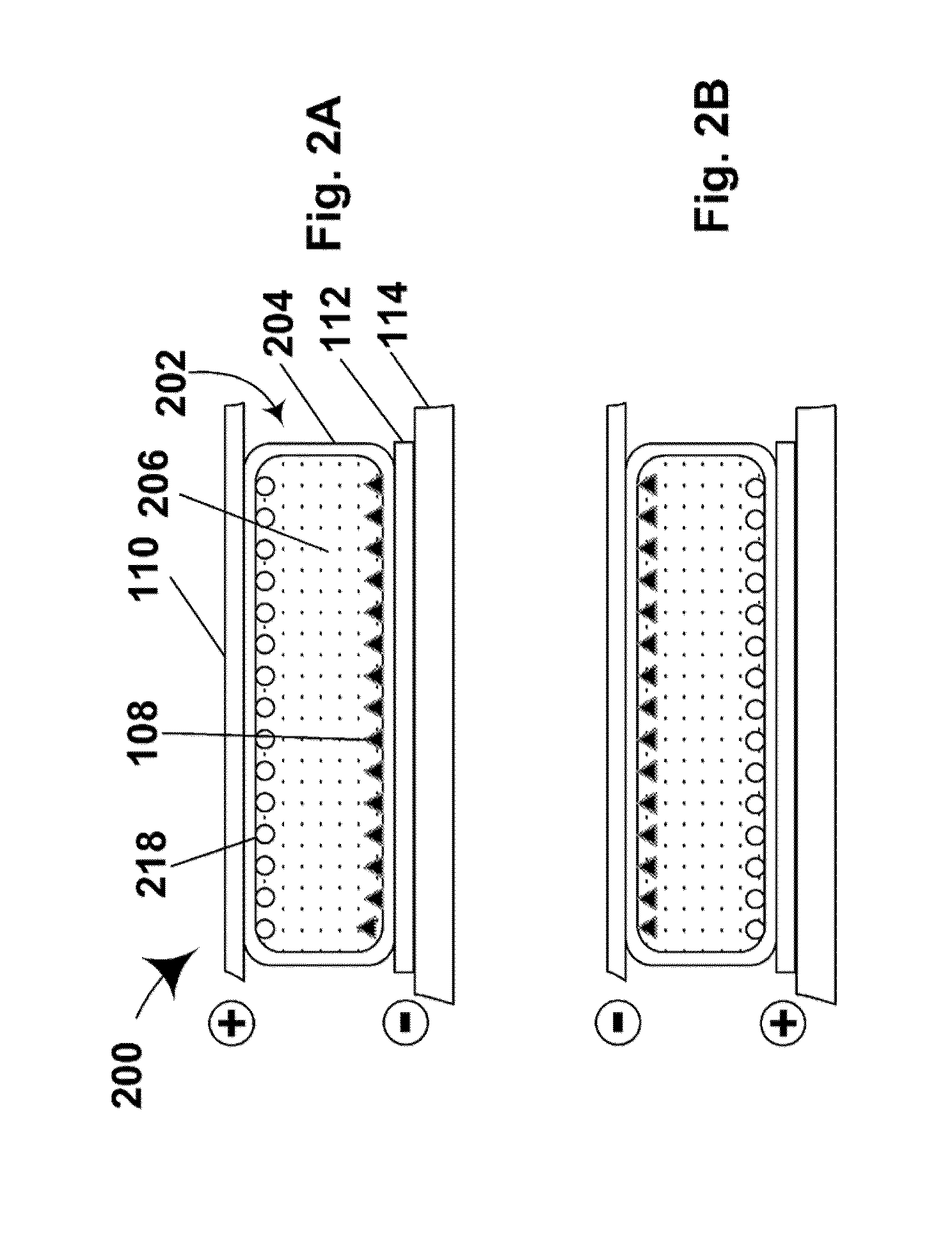

Image

  • Electrophoretic particles and processes for the production thereof
  • Electrophoretic particles and processes for the production thereof
  • Electrophoretic particles and processes for the production thereof

Examples


example 1

Preparation of White Titania Pigment Containing 2,2,2-trifluoroethyl Methacrylate and Lauryl Methacrylate in the Polymer Shell

[0064]DuPont R-794 titania, surface functionalized with 3-(trimethoxysilyl)propyl methacrylate was prepared substantially as described in the aforementioned PCEP applications. In a 1 L plastic bottle, 500 g of this pigment was dispersed in 426 g (500 mL) of toluene by sonication. A 1 L jacketed glass reactor was charged with 1.7158 moles of monomer divided between lauryl methacrylate and TFEM to yield the desired molar concentrations of each monomer. The molar proportions of TFEM were 0.1, 1, 5, 10, 25, and 50 mole % with the remainder being lauryl methacrylate. The pigment dispersion was added to the reactor, and the reactor was purged with nitrogen and heated to 65° C. A free-radical initiator (5.0 g of 2,2′-azobis(2-methylpropionitrile, AIBN), previously dissolved in 110 mL of toluene, was added dropwise over 60 minutes. The vessel was heated under nitroge...

example 2

Preparation of Displays Using Electrophoretic Particles of the Present Invention

[0066]The polymer-coated titania particles prepared in Example 1 above were converted to electrophoretic displays in the following manner.

[0067]Part A : Preparation of capsules

[0068]Gelatin-acacia microcapsules were prepared using the pigments prepared in Example 1 and the following procedure. An internal phase was prepared by combining the following in a 250 mL plastic bottle:

[0069]

ComponentAmount55% BK-444 based Black25.88gPigment(see copendingapplication Ser. No.61 / 150,827, filed Feb. 9,2009) / Isopar E60 wt % White Pigment / Isopar106.77gE:13 wt % polyisobutylene / Isopar7.73gE:10 wt % Solsperse 17K / Isopar23.49gE:Isopar E:10.12g

The resultant mixture was then converted to gelatin-acacia microcapsules substantially as described in the aforementioned U.S. Pat. No. 6,822,782, Examples 27-29.

[0070]Part B: Preparation of displays

[0071]The microcapsules prepared in Part A above were allowed to stand and excess wa...

example 3

Electro-optic Tests

[0073]Electro-optical measurements were take on the single pixel displays prepared in Example 2 using a PR-650 SpectraScan Colorimeter. In these tests, the displays were repeatedly driven to their black and white extreme optical states using 250 millisecond 15 V pulses, then driven to either their black or white extreme optical state. The reflectivity of the optical state was measured about 3 seconds after the final drive pulse (to allow certain transient effects to pass) and then 2 minutes after the final drive pulse, and the two measurements compared to detect any image instability (i.e., lack of bistability in the image).

[0074]The results are shown in FIG. 6 (in which “DS” refers to dark state and “WS” to white state—the white state image instability values are negative since image instability in the white state results in lower reflectivity), from which it will be seen that there is a noticeable increase in image instability as the level of TFEM in the polymer...


PUM

PropertyMeasurementUnit
diametersaaaaaaaaaa
diametersaaaaaaaaaa
weightaaaaaaaaaa

Abstract

In electrophoretic media, it is advantageous to use pigment particles having a polymer chemically bonded to, or cross-linked around, the pigment particles, the polymer comprising repeating units derived from a fluorinated acrylate or fluorinated methacrylate monomer. The polymer desirably has a branched chain structure with side chains extending from a main chain. Desirably, the fluorinated acrylate or fluorinated methacrylate monomer comprises from 1 to 5 mole percent of the polymer.

Description

REFERENCE TO RELATED APPLICATIONS[0001]This application claims benefit of provisional application Ser. No. 61 / 187,370, filed Jun. 16, 2009. This application is also a continuation-in-part of application Ser. No. 12 / 188,648, filed Aug. 8, 2008 (Publication No. 2009 / 0009852), which is a continuation-in-part of application Ser. No. 11 / 673,269, filed Feb. 9, 2007 (now U.S. Pat. No. 7,411,720, issued Aug. 12, 2008), which is a divisional of application Ser. No. 10 / 711,278, filed Sep. 7, 2004 (Publication No. 2005 / 0018273, now abandoned), which is itself a divisional of application Ser. No. 10 / 063,803, filed May 15, 2002 (now U.S. Pat. No. 6,822,782, issued Nov. 23, 2004), which itself claims priority from Provisional Application Ser. No. 60 / 291,081 filed May 15, 2001. The entire disclosures of all these earlier applications, which may hereinafter for convenience be referred to as the “polymer-coated electrophoretic particle” or “PCEP” applications, are herein incorporated by reference.BA...

Claims


Application Information

Patent Timeline
Patent Type & Authority Patents(United States)
IPC IPC(8): G02B26/00G02F1/167
CPCG02F1/167G02F2001/1678
Inventor WALLS, MICHAEL D.FEICK, JASON D.WHITESIDES, THOMAS H.
Owner E INK CORPORATION
Why Eureka
Try Eureka