Sap flow sensor apparatus

a technology of sap flow and sensor, which is applied in the direction of volume/mass flow measurement, measurement devices, instruments, etc., can solve the problems of no commercial products developed in the art, no actual demand for such commercial qs-measurement solutions, and no heat gain nor heat loss from heat storage, so as to prevent the ingress of rainwater, facilitate the running of water droplets, and prevent the accumulation of condensate

Active Publication Date: 2013-11-26
VAN BAVEL MICHAEL
View PDF6 Cites 17 Cited by
  • Summary
  • Abstract
  • Description
  • Claims
  • Application Information

AI Technical Summary

Benefits of technology

[0034]Preferred embodiments thus comprise specially configured insulation having multiple functional layers emplaced in situ circumferentially of the secured inner sensor layer subsequent to the sensor layer, in turn, having been emplaced in situ circumferentially of the plant stem or the like. A particularly effective insulation layer comprises Insul-Tube® soft-cell foam manufactured by Halstead of North Carolina, wherein its closed-cell insulating properties derive from a matrix having a plethora of small-diameter holes. To sustain the integrity of this soft-cell foam material, it is preferable to seal its edges by applying a suitable resin coating exemplified by Halstead “67×44” synthetic resin. It will be appreciated that a unique advantage of the present invention will be seen to be that this multi-layered insulation functionality can be deemed to be an easily-replaced consumable, if damaged, whereupon replacement may be routinely effectuated.
[0035]On an outer layer of this multi-layered insulation, there should preferably be emplaced a membrane cloth permeable to water vapor, but impermeable to water drops. This membrane cloth surrounds both the innermost sensor layer and the circumscribing insulation layers, thereby preventing ingress of rainwater, while simultaneously allowing water vapor flux to exit to the surrounding ambient, while also preventing accumulation of condensate within the sensor. Accordingly, water vapor exits the sensor area through the vapor-permeable layer while the circumscribing layer sheds water that condenses on a sheath between the sensor insulation and the reflective material disposed on the sensor's outermost layer. It has been observed that embodiments of the present invention facilitate water droplets running down the outer layers to ground.
[0036]In an alternate embodiment of the present invention, an angled configuration of thermocouples may be embedded within the cork substrate in the flexible innermost wiring layer, in order to achieve even greater thermocouple-to-plant stem contact than would otherwise be practicable.
[0037]It is accordingly an object of the present invention to provide a means and method for measuring the sap flow in the stems of herbaceous plants and trees while reducing or removing NTG effects.
[0038]It is also an object and advantage of the present invention to determine the sap flow of herbaceous plants and trees accurately and non-intrusively by invoking an in situ apparatus having simpler construction and concomitant wiring than has been heretofore known in the art.
[0039]It is another object and advantage of the present invention to assemble a sap flow measuring apparatus in situ using a single wrapping of heat-sensing electronics and an integrated heater, forming an exoskeleton configuration which is then engulfed, in turn, within multi-layer insulation and an external infrared radiation shield layer.

Problems solved by technology

But, as is known to practitioners in the art, a deficiency of such implementation has been that neither heat gain nor heat loss from heat storage in the sensor's measurement section has been considered in this sap flow calculation.
Unfortunately, there have been no commercial products developed in the art that have engendered economic construction and / or an economic recording methodology.
Moreover, there appears to have been no actual demand heretofore for such commercial Qs-measurement solutions.
Problems with sap flow measurements under field conditions have been reported in published literature related to moisture and adventitious root development in plants such as corn, willow, and poplar trees.
Even in arid climates, characterized by inherently high evapotranspiration, plants transpire though their respective stems while moisture accumulation causes thermocouple damage over time.
Moreover, unpublished reports emanating from the University of Arizona have described damage to sensors caused by moisture accumulation thereon, when such sensors have been installed on willow and poplar.
In particular, it has been observed that moisture accumulation causes bark damage effectuated by mold and mildew, tending to cause consequential damage to sensor coatings and to implicated insulating collars.
Eventually, corrosion causes damage to crucial sensing thermocouples and associated thermopile electronics.
Since such corrosion damage is obviously irreparable, costly replacement of entire sap flow sensors would be required to sustain accurate field measurements of sap flow.
Accordingly, commercial services providing sap flow data have heretofore required costly recurring maintenance of sap flow sensors in the field.
Practitioners in the art have been challenged by a long-standing deficiency that sap flow apparatus seeking to commercially measure sap flow in corn, soybean, cotton, tomato, and many other crops lack a convenient and expeditious installation methodology that is not only inherently flexible and adaptable, but also affords significantly less-frequent maintenance and routinely effectively seals electronic wiring.
As is well known to practitioners skilled in the art, a substantial portion of sensor construction cost has been attributable to labor associated with assembling prerequisite electronics.
But, another substantial portion of sap flow measurement cost is attributable to construction of a reliable integrated sensor collar that includes and encompasses the contemplated number of electrical connections prerequisite for computing the energy balance from which sap flow may be converted.
Signal processing data loggers, e.g., the “Flow4” System disclosed in U.S. Pat. No. 7,280,892, incorporated herein fully by reference, have proven to be relatively expensive due to the necessity for four differential channels required for each sensor connection.
This demanding requirement and other factors render such monitoring apparatus rather expensive, thereby foreclosing many commercial applications which would clearly benefit from implementations of such Flow4 technology.
When early morning conditions were studied, NTG manifest as differences in air and sap temperatures, and the release of stored heat, Qs, causing problematic sap flow results having substantial peaks.
Published research and computer simulations apparently have nevertheless not accommodated installations that typically require overlap of the sensor heater, which, in turn, inevitably causes an uneven distribution of heat across the plant's stem.
The sap flow means and techniques heretofore known by those skilled in the art have suffered from a panoply of deficiencies: failing to remove or diminish the effects of NTG; manifesting concerns for moisture damage to both plant and sensor; unreliably installing and implementing sensors over irregular plant surfaces; and requiring at least four data channels.
This panoply of deficiencies has continued to render current sap flow detection and measurement technology unaffordable in many beneficial scenarios.

Method used


Image

  • Sap flow sensor apparatus
  • Sap flow sensor apparatus
  • Sap flow sensor apparatus

Examples


Embodiment Construction

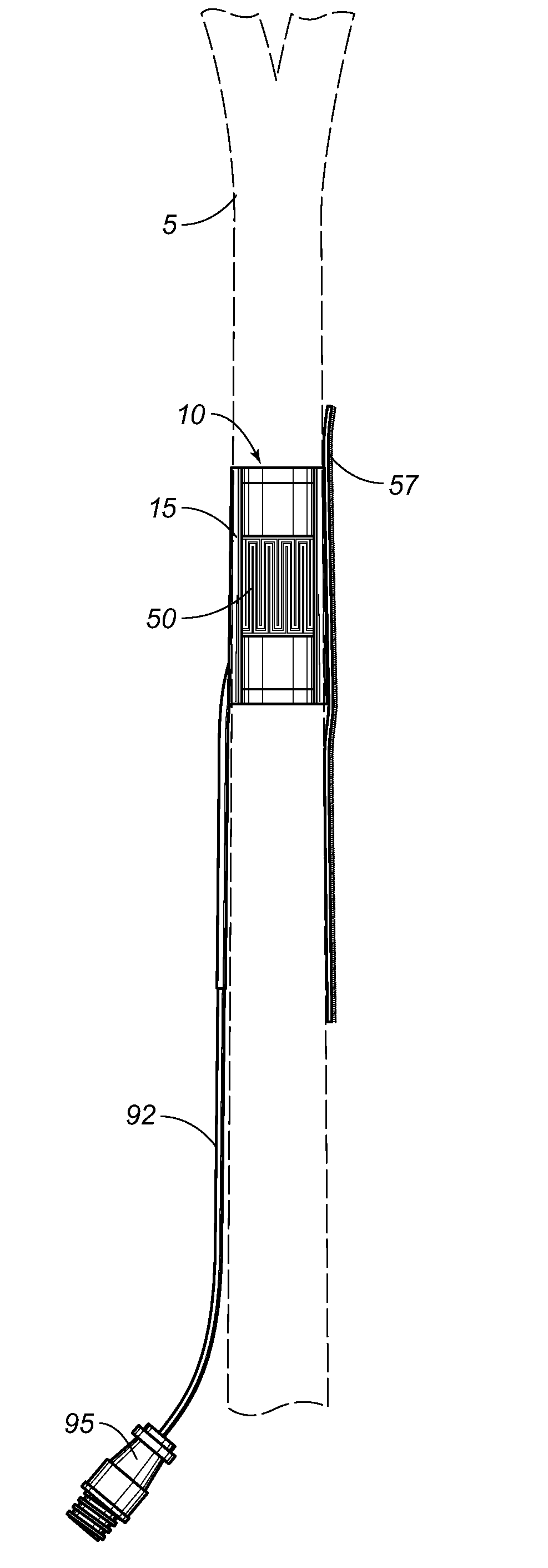
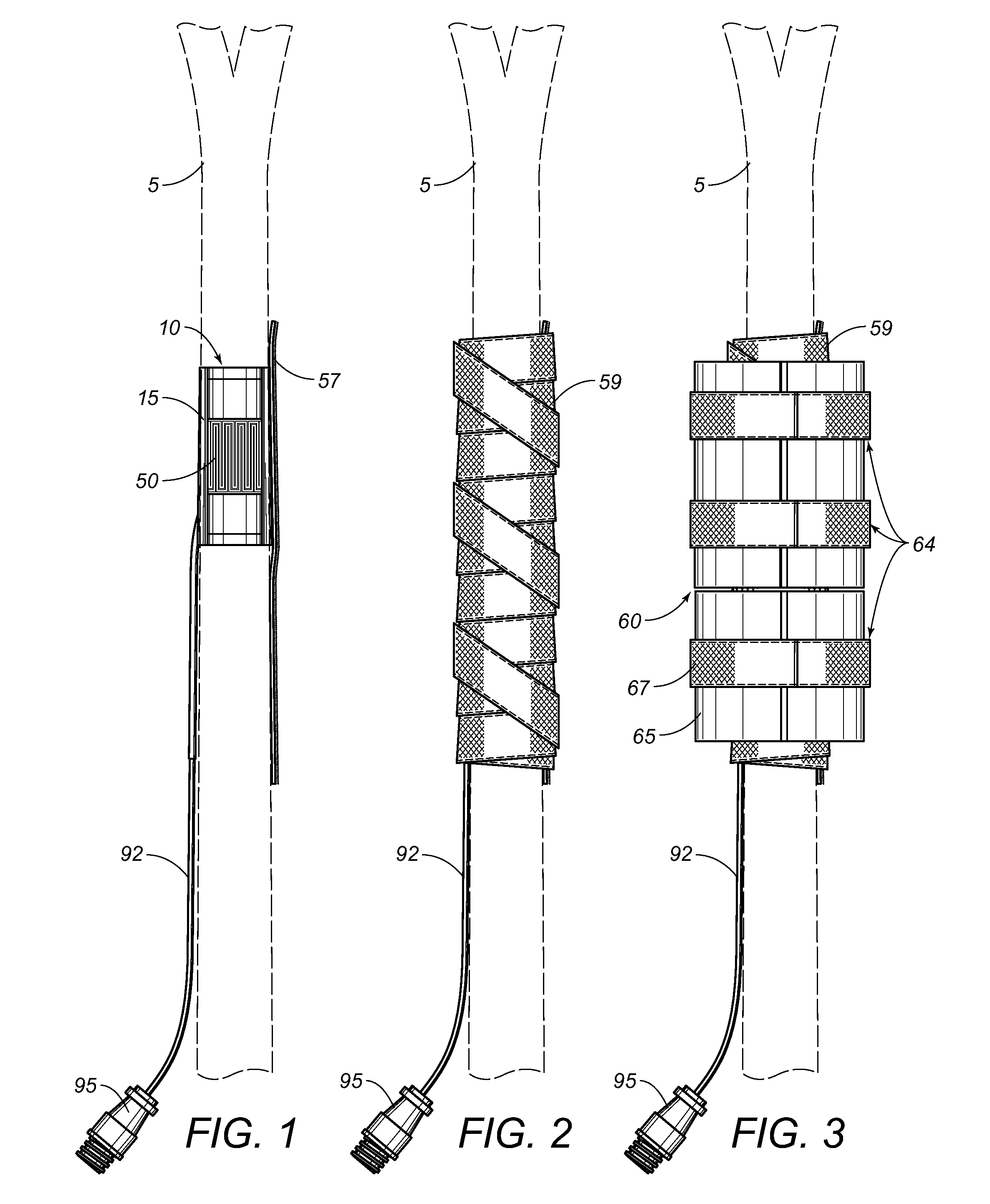
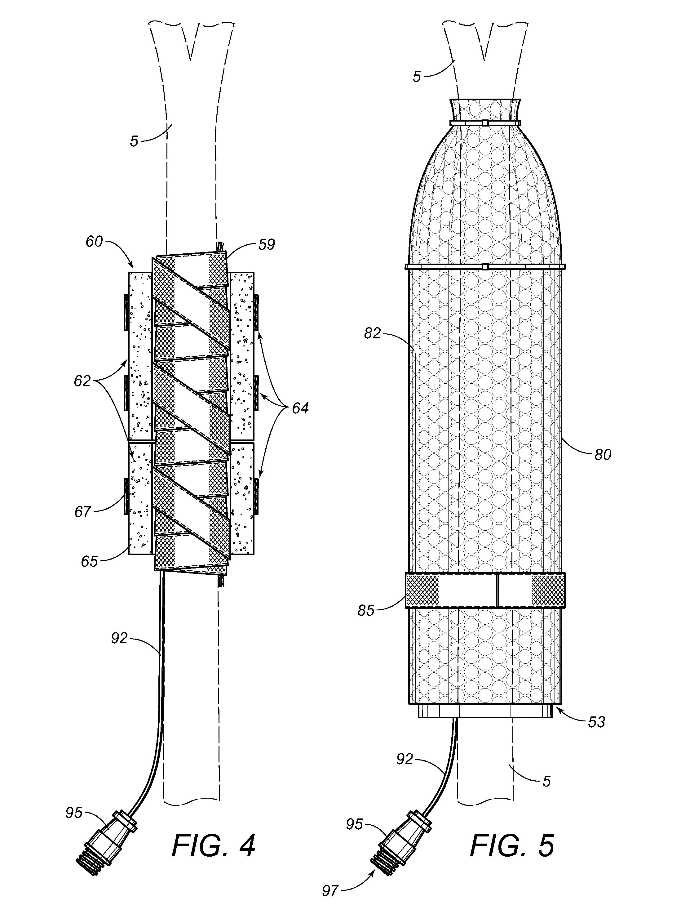
[0064]Reference is made herein to the figures in the accompanying drawings in which like numerals refer to like components. Now referring to FIGS. 1-7, there are depicted multiple frontal views of the preferred embodiment of the present sap flow sensor apparatus using iSHB methodology taught hereunder. Effectuating a significant departure from the current art, the present invention preferably collects only one reading of dT, thereby eliminating the need to read Qu and Qd, since all of the conduction energy losses are grouped or lumped together into one value, Qc. As will be herein described in detail, this new Qc value is determined from a radial thermopile imbedded in electronics assembly body member 10 (exposed in cut-away view in FIG. 1), which is assumed to constitute all heat conduction which has been experimentally corroborated as will be hereinafter elucidated.

[0065]It has been found that Qv typically constitutes 10 to 20% of the Qr value, and, if the two values are combined ...


PUM


Abstract

Sap flow sensor apparatus and concomitant methodology for determining the sap flow within plant stems of herbaceous plants and trees using a simplified Stem Heat Balance methodology. Optimum irrigation and utilization of beneficial plant health statistics are enabled using a sap flow sensor apparatus configured with a flexible, sealed sensor layer and multi-layered insulation including an elastic hook-and-loop attachment for enclosing the flexible, sealed sensor layer, soft-foam insulation, a waterproof membrane cloth permeable to water vapor and impermeable to water drops, and an outermost reflective barrier. Based upon the calculations derived from the simplified Stem Heat Balance formula, embodiments afford operational and economic efficiencies due to reduction of the prerequisite electronics to a 1-Channel dT signal.

Description

RELATED APPLICATIONS[0001]This application claims priority based upon Provisional U.S. Application Ser. No. 61 / 352,233 filed Jun. 7, 2010.FIELD OF THE INVENTION[0002]The present invention relates to an apparatus for measuring sap flow in plants and the like, and more particularly, relates to an apparatus configured with an exoskeleton electronics interior layer and concentric multi-layered insulation, for in situ installation in the field in order to directly and accurately measure sap streams in herbaceous plants and trees without the necessity for empirical calibration or for stem intrusion.BACKGROUND OF THE INVENTION[0003]The Stem Heat Balance (“SHB”) method of estimating sap flow within a plant stem has been well established as being an accurate methodology applicable to sap flow behavior in many species under a diversity of field conditions. For instance, Lascano, Baumhhardt, and Lipe reported that consistent results had been obtained for grapevines during a 2-day period with o...

Claims


Application Information

Patent Timeline
Patent Type & Authority Patents(United States)
IPC IPC(8): G01F1/68
CPCG01F1/6888G01F1/6847
Inventor VAN BAVEL, MICHAEL
Owner VAN BAVEL MICHAEL
Why Eureka
Try Eureka