
Red-emitting nitride-based calcium-stabilized phosphors

a technology of calcium-stabilized phosphor and red nitride, which is applied in the direction of discharge tube luminescent screen, discharge tube/lamp details, luminescent composition, etc., can solve the problems of poor stability of red nitride phosphor, and do oxygen-containing phosphor materials exhibit poor stability, and achieve beneficial effects, improve temperature and humidity stability, and enhance physical properties of phosphor

Active Publication Date: 2013-12-03
INTEMATIX
View PDF81 Cites 57 Cited by
  • Summary
  • Abstract
  • Description
  • Claims
  • Application Information

AI Technical Summary

Benefits of technology

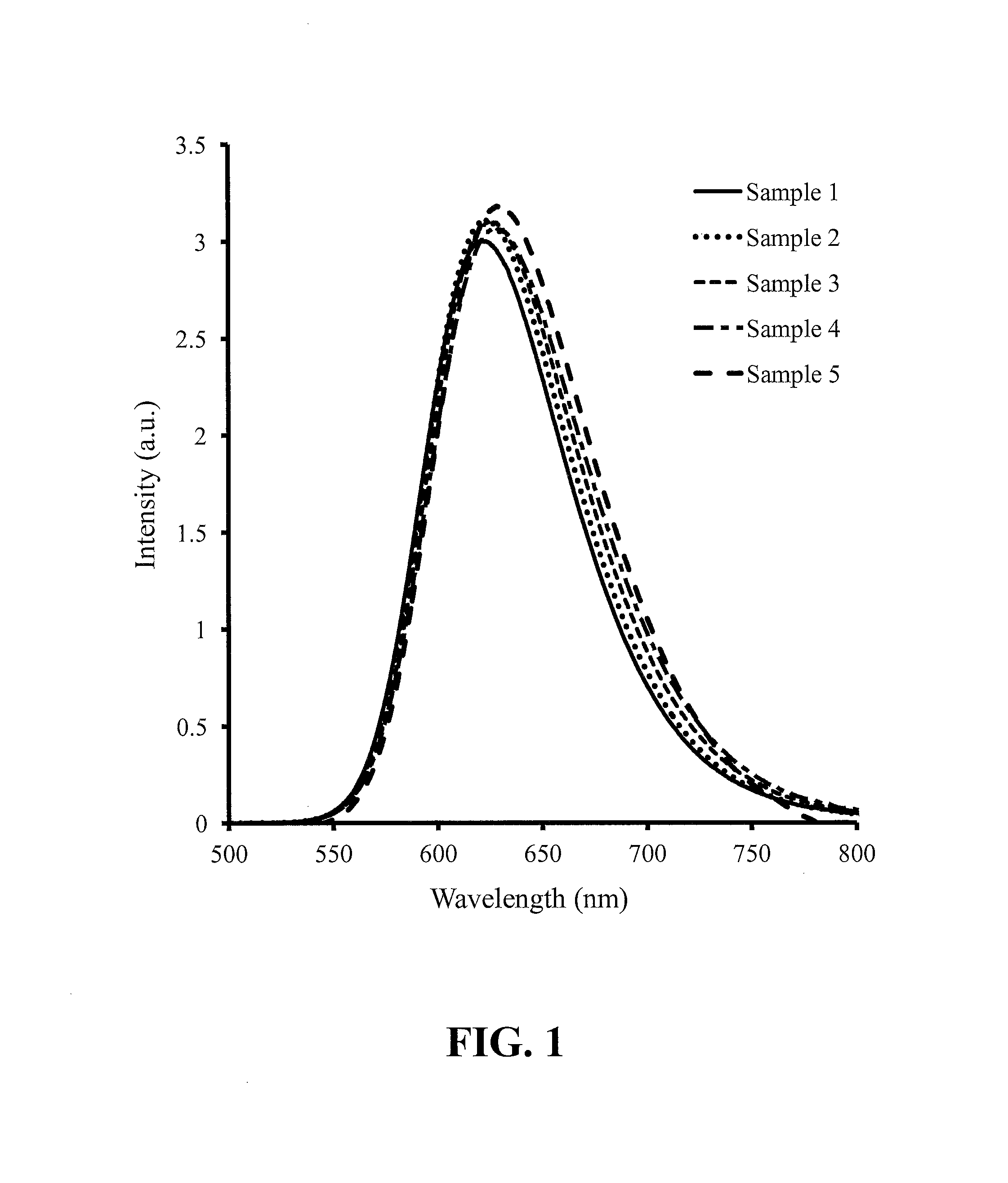
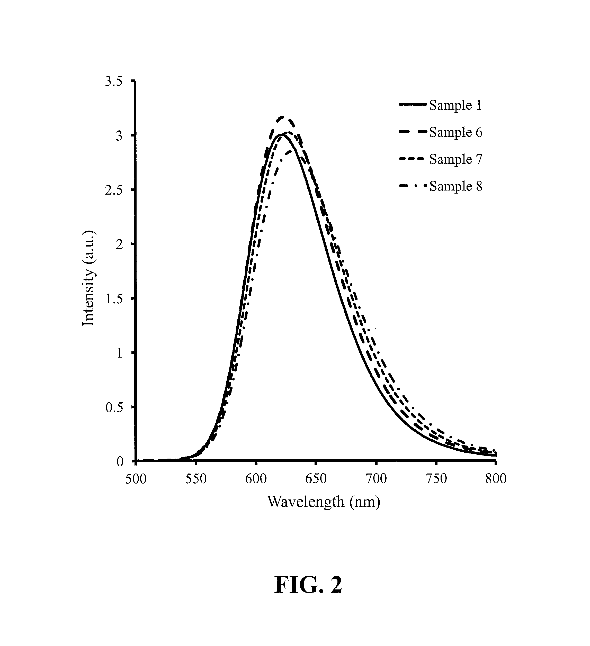
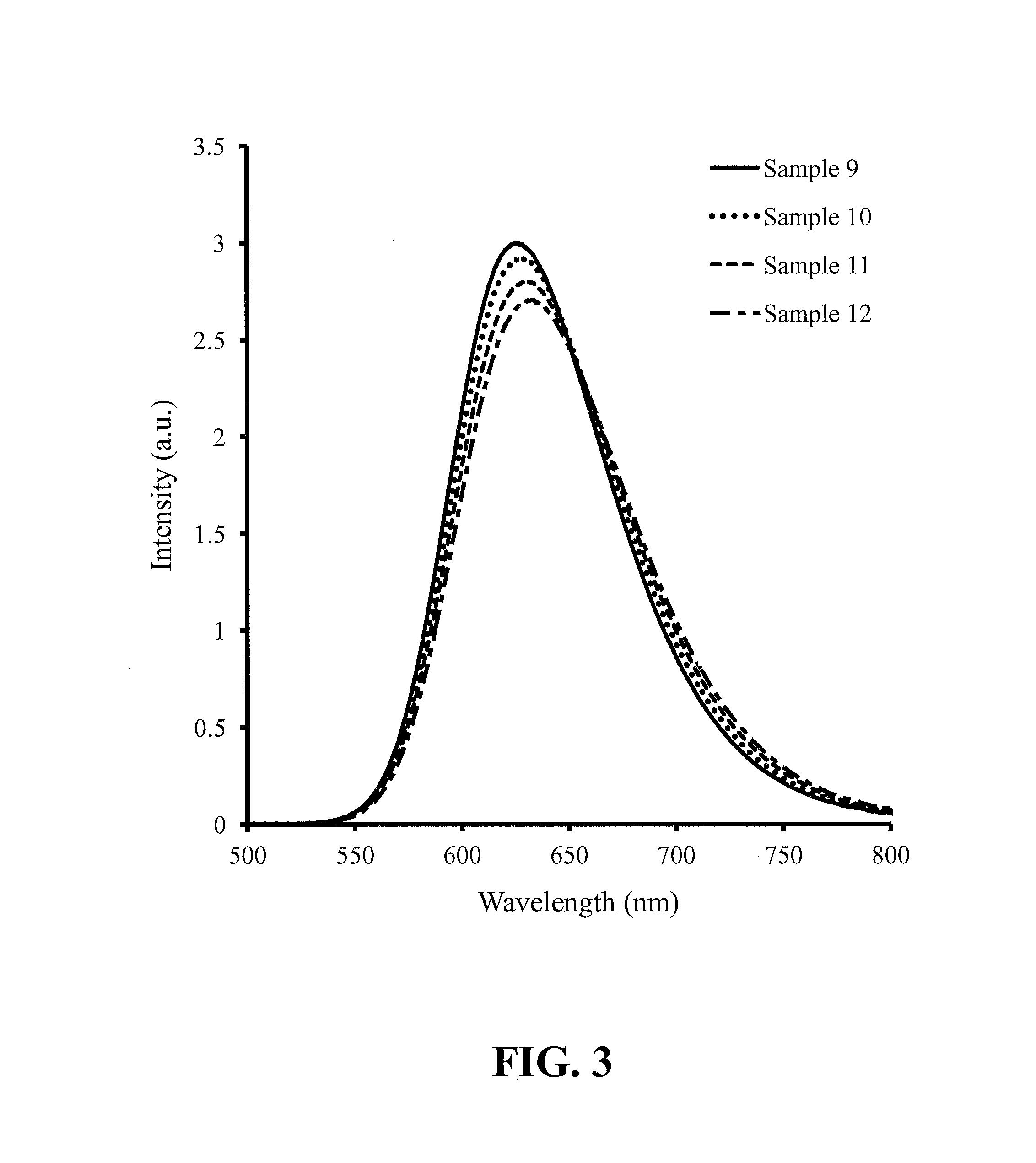
The present invention provides nitride-based phosphors that are stabilized, particularly with calcium, and can be used to extend the peak emission wavelength to longer wavelengths in the red while also improving physical properties, such as stability under high temperatures and humidity. The phosphor materials have a composition that incorporates interstitial calcium which enhances their stability under these conditions. After aging at elevated temperature and humidity, the phosphor maintains its photoluminescent intensity and chromaticity coordinates within certain ranges.

Problems solved by technology

However, this red nitride phosphor has poor stability when used as a coating on an LED operated at a temperature in the range from 60° C. to 120° C. and an ambient relative humidity in the range from 40% to 90%.
However, these oxygen containing phosphor materials are known to exhibit poor stability under the combined conditions of high temperature and high relative humidity (RH)—for example 85° C. and 85% RH.
The forms of charge compensation reported in the art are not believed to render the phosphor more impervious to thermal / humidity aging, nor do they appear to accomplish the beneficial result of increasing the peak emission wavelength with little or substantially no alteration of photoemission intensity.

Method used


Image

  • Red-emitting nitride-based calcium-stabilized phosphors
  • Red-emitting nitride-based calcium-stabilized phosphors
  • Red-emitting nitride-based calcium-stabilized phosphors

Examples


Embodiment Construction

[0037]Embodiments of the present invention will now be described in detail with reference to the drawings, which are provided as illustrative examples of the invention so as to enable those skilled in the art to practice the invention. Notably, the figures and examples below are not meant to limit the scope of the present invention to a single embodiment, but other embodiments are possible by way of interchange of some or all of the described or illustrated elements. Moreover, where certain elements of the present invention can be partially or fully implemented using known components, only those portions of such known components that are necessary for an understanding of the present invention will be described, and detailed descriptions of other portions of such known components will be omitted so as not to obscure the invention. In the present specification, an embodiment showing a singular component should not be considered limiting; rather, the invention is intended to encompass ...


PUM


Abstract

Red-emitting phosphors may comprise a nitride-based composition represented by the chemical formula MaSrbSicAldNeEuf, wherein: M is at least one of Mg, Ca, Sr, Ba, Y, Li, Na, K and Zn, and 0<a<1.0; 1.5<b<2.5; 4.0≦c≦5.0; 0≦d≦1.0; 7.5<e<8.5; and 0<f<0.1; wherein a+b+f>2+d / v and v is the valence of M. Furthermore, nitride-based red-emitting phosphor compositions may be represented by the chemical formula MxM′2Si5−yAlyN8:A, wherein: M is Mg, Ca, Sr, Ba, Y, Li, Na, K and Zn, and x>0; M′ is at least one of Mg, Ca, Sr, Ba, and Zn; 0≦y≦0.15; and A is at least one of Eu, Ce, Tb, Pr, and Mn; wherein x>y / v and v is the valence of M, and wherein the red-emitting phosphors have the general crystalline structure of M′2Si5N8:A.

Description

CROSS-REFERENCE TO RELATED APPLICATIONS[0001]This application is a continuation-in-part of U.S. patent application Ser. No. 13 / 871,961 filed Apr. 26, 2013, and claims the benefit of U.S. Provisional Application No. 61 / 673,191 filed Jul. 18, 2012. The disclosures of the aforementioned applications are all incorporated by reference in their entirety herein.FIELD OF THE INVENTION[0002]Embodiments of the present invention are directed to red-emitting nitride-based phosphor compositions.BACKGROUND OF THE INVENTION[0003]Many of the red-emitting phosphors are derived from silicon nitride (Si3N4). The structure of silicon nitride comprises layers of Si and N bonded in a framework of slightly distorted SiN4 tetrahedra. The SiN4 tetrahedra are joined by a sharing of nitrogen corners such that each nitrogen is common to three tetrahedra. See, for example, S. Hampshire in “Silicon nitride ceramics—review of structure, processing, and properties,”Journal of Achievements in Materials and Manufact...

Claims


Application Information

Patent Timeline
IPC IPC(8): C09K11/59H01L33/00
CPCC09K11/0883C09K11/7731C09K11/7734H05B33/14C09K11/7728H05B33/12H01L33/50H01L2224/73265H01L2224/48091H01L2224/48247H01L2224/49107H01L2924/00014C09K11/77348C09K11/77C09K11/08H01L33/32H01L33/504H01L33/507H01L33/56H01L33/62
Inventor LIU, SHENGFENGLI, YI-QUNLEUNG, KA Y.TAO, DEJIE
Owner INTEMATIX
Learn More