Looped airfoil wind turbine

a wind turbine and airframe technology, applied in the direction of electric generator control, machines/engines, mechanical equipment, etc., can solve the problems of complex and expensive production of rotor blades, constant maintenance, and complex mechanisms for turning turbines into wind turbines

Active Publication Date: 2013-12-31
EVERELEVATOR WIND TECH
View PDF5 Cites 11 Cited by
  • Summary
  • Abstract
  • Description
  • Claims
  • Application Information

AI Technical Summary

Benefits of technology

[0006]In a LAWT system, the three long blades of a typical conventional rotor are replaced by many shorter wing segments. In effect, each rotor blade is reshaped into several more efficient wing segments with a traditional wing profile. Each wing segment has a constant profile along its entire length, greatly reducing the manufacturing costs when compared to the blades of the wind turbine's rotor where the blade profile varies along its length. The LAWT wing segments can be either symmetrical or asymmetrical leading to various trade-offs useful in the different market niches.
[0009]In an embodiment, all wings travel on wheels, such as rollercoaster-like wheels or small (wheelbarrow-like) tires riding on “travel tracks.” The wings are connected, as by a segmented chain which transfers the kinetic power of wheeled wings directly to multiple generators, requiring no gears. The number of wing segments is limited only by the length of the device's travel tracks. Each wing is attached at both ends making the construction sturdier and less expensive. Additionally, the LAWT system is fully scalable. Its height and width can be scaled independently.
[0012]With asymmetrical (cambered airfoil) profiled wings, no pitch adjustment mechanism will be required and pitch may be fixed. Cambered airfoils have an advantage of almost doubling the lift performance of symmetrical airfoils in the positive pitch range, but are very inefficient as “spoilers” in the negative pitch range. Lift force and drag force will be provided by the ascending wings in the front while descending wings will provide largely drag force and some smaller non-aerodynamic (“barn door”) negative lift.
[0014]Single wings typically require up to 4 wheels each. To reduce the total number per one system, it may be advantageous to “group” 2 or more wings closer together on a single 4-wheel rectangular frame. Such airfoil “grouping” will be aerodynamically similar to old bi-planes or tri-planes, resulting in maximum lift-force density per square meter of the frontal area and overall reduction of moving parts.
[0018]Optional yaw mechanism will be at the bottom of the triangular structure. As usual, such mechanism insures a proper orientation to face the wind. Conventional yaw implementations are possible, but they generally involve expensive planetary gears. The wide base of the structure opens the possibility of unconventional implementations, for example, a circular arrangement of car tires riding in a wide circle with the diameter similar to the base length or width. Although a conventional rudder may be used, rudderless yaw may be achieved by an off-center yaw rotation. By placing the yaw rotation center (the center of rotation of the base around a vertical axis) ahead of the center of the triangular structure, the device will automatically orient itself with the ascending wings facing the wind. It also eliminates the need to lock the yaw position of the device as is required by a conventional wind turbine.

Problems solved by technology

This makes production of the rotor blades very complex and expensive.
Moreover, mechanisms to turn the turbine into the wind are complex and subject to constant maintenance

Method used


Image

  • Looped airfoil wind turbine
  • Looped airfoil wind turbine
  • Looped airfoil wind turbine

Examples


Embodiment Construction

[0037]The following detailed description illustrates the invention by way of example and not by way of limitation. This description will clearly enable one skilled in the art to make and use the invention, and describes several embodiments, adaptations, variations, alternatives and uses of the invention, including what I presently believe is the best mode of carrying out the invention. As various changes could be made in the above constructions without departing from the scope of the invention, it is intended that all matter contained in the above description or shown in the accompanying drawings shall be interpreted as illustrative and not in a limiting sense.

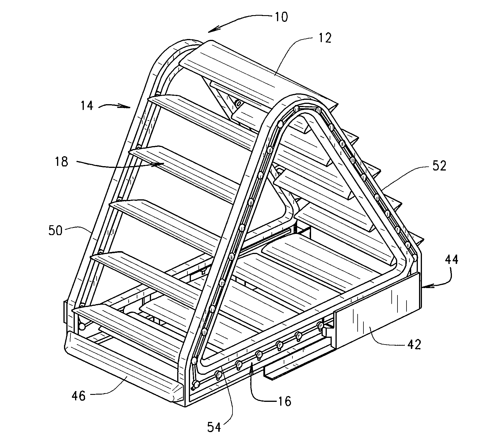
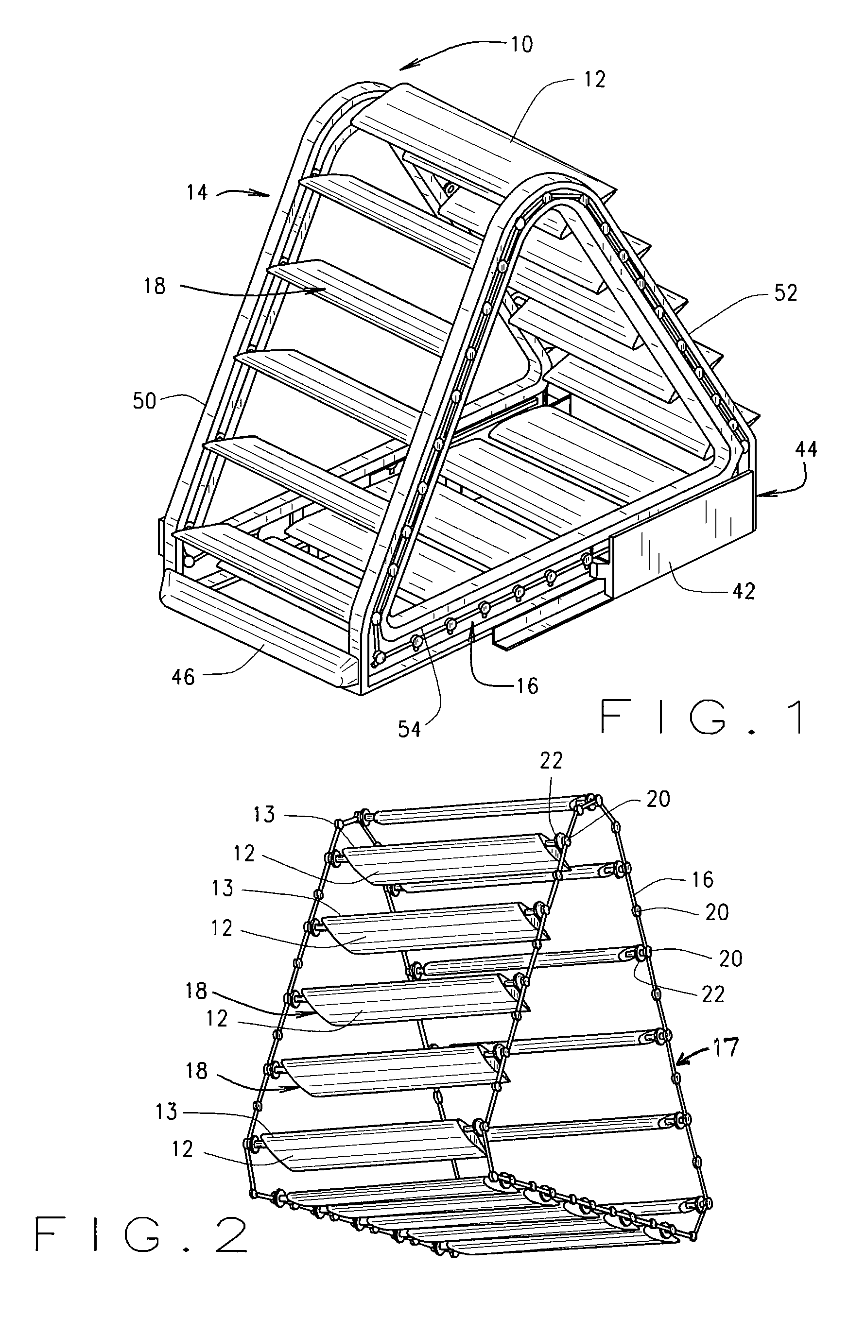
[0038]As shown in FIGS. 1 and 2, a LAWT system 10 of the present invention replaces the three long blades of the typical conventional rotor with many shorter wing segments 12 which move linearly around a triangular support structure 14. The wing segments 12 are the major parts of carriages 18 which are interconnected to each o...


PUM


Abstract

Looped AirFoil Wind Turbine (LAWT) (10) is a novel wind turbine with a basic system of a triangular structure (14) utilizing both lift and drag aerodynamic forces produced by wind energy. The entire triangular structure (14) could either yaw to always face the wind direction (W) or stay in a fixed position. The LAWT system (10) uses airfoil blades (12) shaped like an airplane wing, traveling linearly on travel wheels (22) riding on travel tracks (50, 52, 54). While traveling up, the wings are powered by a positive lift force and drag force while using negative lift force and drag force when traveling downward. All wings (12) are connected by a segmented chain (16) which transfers the kinetic power of wheeled wing carriages (18) directly to multiple generators (26), requiring no gears.

Description

RELATED APPLICATIONS[0001]This application is related to U.S. Provisional Patent Application No. 61 / 157,093, filed Mar. 3, 2009, and U.S. Provisional Patent Application No. 61 / 309,601, filed Mar. 2, 2010, from both of which priority is claimed, and the disclosures of which are hereby incorporated by reference, and is a national stage application under 35 U.S.C. §371 of PCT application US / 2010 / 026054, filed Mar. 3, 2010.TECHNICAL FIELD[0002]This invention relates to a device for extracting power, preferably electrical power, from wind.BACKGROUND ART[0003]Conventional wind turbines are powered by a rotor with blades shaped and arranged similarly to a helicopter rotor. The blade profile of a conventional wind turbine's rotor varies along its length, similar to a helicopter rotor. This makes production of the rotor blades very complex and expensive. Moreover, mechanisms to turn the turbine into the wind are complex and subject to constant maintenanceSUMMARY OF THE INVENTION[0004]Looped ...

Claims


Application Information

Patent Timeline
Patent Type & Authority Patents(United States)
IPC IPC(8): F03D9/02
CPCF05B2260/76Y02E10/725F03D5/02Y02E10/70F05B2260/79F03D9/002F03D9/25Y02E10/72
Inventor SYROVY, GEORGE, J.
Owner EVERELEVATOR WIND TECH
Why Eureka
Try Eureka