Method of injecting carbon dioxide

a carbon dioxide and injection method technology, applied in the field of injection methods, can solve the problems of undesirable release of carbon dioxide into the atmosphere, loss of cosub>2 /sub, and loss of cosub>2 /sub, and achieve the effects of reducing injection costs, reducing injection costs, and greater cost of compressing a vapour stream

Active Publication Date: 2014-01-07
BP EXPLORATION OPERATING CO LTD
View PDF22 Cites 4 Cited by
  • Summary
  • Abstract
  • Description
  • Claims
  • Application Information

AI Technical Summary

Benefits of technology

[0025]The method of the present invention may be used where the hydrocarbon reservoir is penetrated by a plurality of existing gas injection wells and / or “water alternating gas” (WAG) injection wells and hence there is existing gas injection capacity at the injection facility. However, the existing gas injection capacity may be limited owing to the cost of providing additional compressors and coolers, space and weight constraints, particularly on a platform, or limited gas turbine capacity (for providing electricity to drive the gas injection compressors). Accordingly, an advantage of the present invention is that an amount of produced vapour stream that is in excess of the existing gas injection capacity at the injection facility may be recycled to the reservoir by being converted from a vapour state into a dense phase state before being mixed with the imported CO2 stream. Accordingly, there is no requirement to increase the gas injection capacity of the existing injection facility. Typically, converting the excess produced vapour stream from a vapour state into a dense phase state increases the gas handling capacity of the production and injection facilities by up to 250 millions of standard cubic feet of produced vapour per day (mmscfs / d)(7 million cubic metres of produced vapour per day). Typically, the total amount of produced vapour stream that is to be recycled to the reservoir is at least 100 millions of standard cubic feet of produced vapour per day (mmscf / d) (2.8 million cubic metres of produced vapour per day). Thus, a portion of the produced vapour stream (in an amount that is up to the existing gas injection compressor capacity) may be injected in a vapour state into one or more of the existing gas and / or WAG injection wells using the existing gas injection compressor(s). The remainder of the produced vapour stream is converted from a vapour state into a dense phase state before being mixed with the imported CO2 stream thereby forming the co-injection stream. The co-injection stream may then be injected down one or more existing water injection wells and / or into one or more injection wells that have been specifically designed for the injection of the co-injection stream. However, it is envisaged that one or more of the existing gas injection wells and / or WAG injection wells, may be switched to the injection of the co-injection stream thereby increasing the number of injection wells that are available for injecting the co-injection stream.
[0026]It is also envisaged that injection of the produced vapour stream in the vapour state may be eliminated. Thus, the existing gas injection capacity may not be utilized and substantially all of the produced vapour stream that is to be recycled to the reservoir is converted into a dense phase state before being mixed with the imported CO2 stream. The present invention may therefore allow all of the existing gas injection wells and / or existing WAG injection wells to be switched to injection of the co-injection stream thereby providing increased assurance that the imported CO2 may be reliably injected into the reservoir. Thus, there is greater flexibility in the event that one or more (but not all) of the injection wells are shut-in, for example, for maintenance.
[0027]Yet a further advantage of the present invention is that it is possible to handle the large amounts of the produced vapour stream that must be recycled to the reservoir in the absence of any existing gas injection capacity and existing gas injection wells. Thus, it is envisaged that substantially all of the produced vapour stream may be compressed and cooled before being mixed with the imported CO2 stream and all of the injection wells that penetrate the hydrocarbon reservoir (for example, existing water injection wells and / or injection wells that have been specifically designed for the injection of the co-injection stream) are dedicated to the injection of the co-injection stream.
[0028]In addition, a further advantage of the present invention is that compressing and cooling the produced vapour stream (thereby converting the produced vapour stream from a vapour state into a dense phase state) and mixing the resulting cooled stream with the imported CO2 (that is in a liquid state or supercritical state) reduces the injection costs compared with the separate injection of an imported CO2 stream (in a liquid state or supercritical state) and a compressed produced vapour stream into liquid and gas injection wells respectively. This is because the down-hole pressure in an injection well has two components: (a) the well-head pressure and (b) the static head or the weight of the column of fluid in the injection well. The static head of a column of a dense phase fluid in an injection well is significantly higher than that of a column of vapour. Accordingly, the well-head pressure for the co-injection stream is lower than the well-head pressure for a compressed produced vapour stream. Furthermore, the cost of compressing a vapour stream to a higher pressure is greater than the cost of pumping a dense phase stream to a higher pressure.
[0029]A further advantage of the present invention is that injection of the co-injection stream into the hydrocarbon reservoir may result in enhanced recovery of liquid hydrocarbons (oil or gas condensate) therefrom. Enhanced recovery of oil may arise owing to improved sweep efficiency of the dense phase co-injection stream compared with using water as the displacement fluid since the dense phase co-injection stream has a similar viscosity to oil and is therefore less likely to by-pass or finger-through the oil than water. In addition, enhanced recovery of oil may arise owing to the dense phase co-injection stream dissolving oil from the surface of the reservoir rock. Enhanced recovery of gas condensate may arise where the co-injection stream is injected into the lower portion of the gas condensate reservoir.
[0030]Where the produced vapour stream has a low CO2 content of less than 15% by volume, a portion of the produced vapour stream may be used as fuel gas for the production and injection facilities, for example, as fuel gas for one or more electric generators. However, as the concentration of CO2 in the produced vapour stream increases with time this will result in a decrease in the calorific value of the produced vapour stream. Accordingly, a fuel gas may be formed by passing the produced vapour stream (for example, having a CO2 content in excess of 50% by volume or in excess of 75% by volume) through a membrane module to separate a fuel gas having a CO2 content of below 15% by volume. Where the CO2 content of the produced vapour stream is above 75% by volume this will require the processing of a large volume of produced vapour stream. For example, the amount of the produced vapour stream that is used to generate the fuel gas may be in the range of 5 to 10 millions of standard cubic feet of vapour per day (mmscf / d) (0.14 to 0.28 million cubic metres of vapour per day). The reject stream that is enriched in CO2 may be recombined with the remainder of the produced vapour stream prior to compressing the produced vapour stream in step (c) of the present invention. An advantage of recombining the reject stream with the remainder of the produced vapour stream is that the cooled stream that is formed in step (d) will have a higher molecular fraction of CO2. Accordingly, the cooled stream will be of a higher density (than in the absence of recombining the reject stream with the produced vapour stream). Accordingly, the co-injection stream will also be of a higher density and the down-hole pressure will have a higher contribution from the static head of the column of co-injection stream in the injection well.

Problems solved by technology

Release of this by-product into the atmosphere is undesirable as it is a greenhouse gas.
However, the produced CO2 comprises a number of hydrocarbon impurities which affect the saturation pressure of the formation.
Further, US 2002 / 0036086 teaches that sequestration of CO2, which inherently occurs in such a process, is actually a drawback of the process, resulting in a “loss” of CO2 and requiring addition of further CO2.
Thus, for enhanced oil recovery, as taught by US 2002 / 0036086, any CO2 storage that occurs is considered a “loss” and is a disadvantage.
Further, the quantities of CO2 involved in disposal by injection into a hydrocarbon reservoir are immense, generally of the order of millions of tonnes, and significantly more than the amounts involved in enhanced oil recovery.
However, the distance of any injection wells from any production wells may be limited, for example by infrastructure limitations.
In any case, with time the large volume of injected CO2 will start to result in an increase in the amount of produced vapour comprising carbon dioxide recovered from the production well.
Although production wells will often have associated gas injection wells for the purpose of injection of produced vapour comprising CO2, even in the absence of CO2 sequestration, the increasing quantities of vapour comprising CO2 resulting from CO2 sequestration in the reservoir may saturate such facilities, leading to the requirement for more injection wells to be drilled and the cost associated therewith, all for a reservoir that may be well past its peak production.

Method used


Image

  • Method of injecting carbon dioxide
  • Method of injecting carbon dioxide

Examples


Embodiment Construction

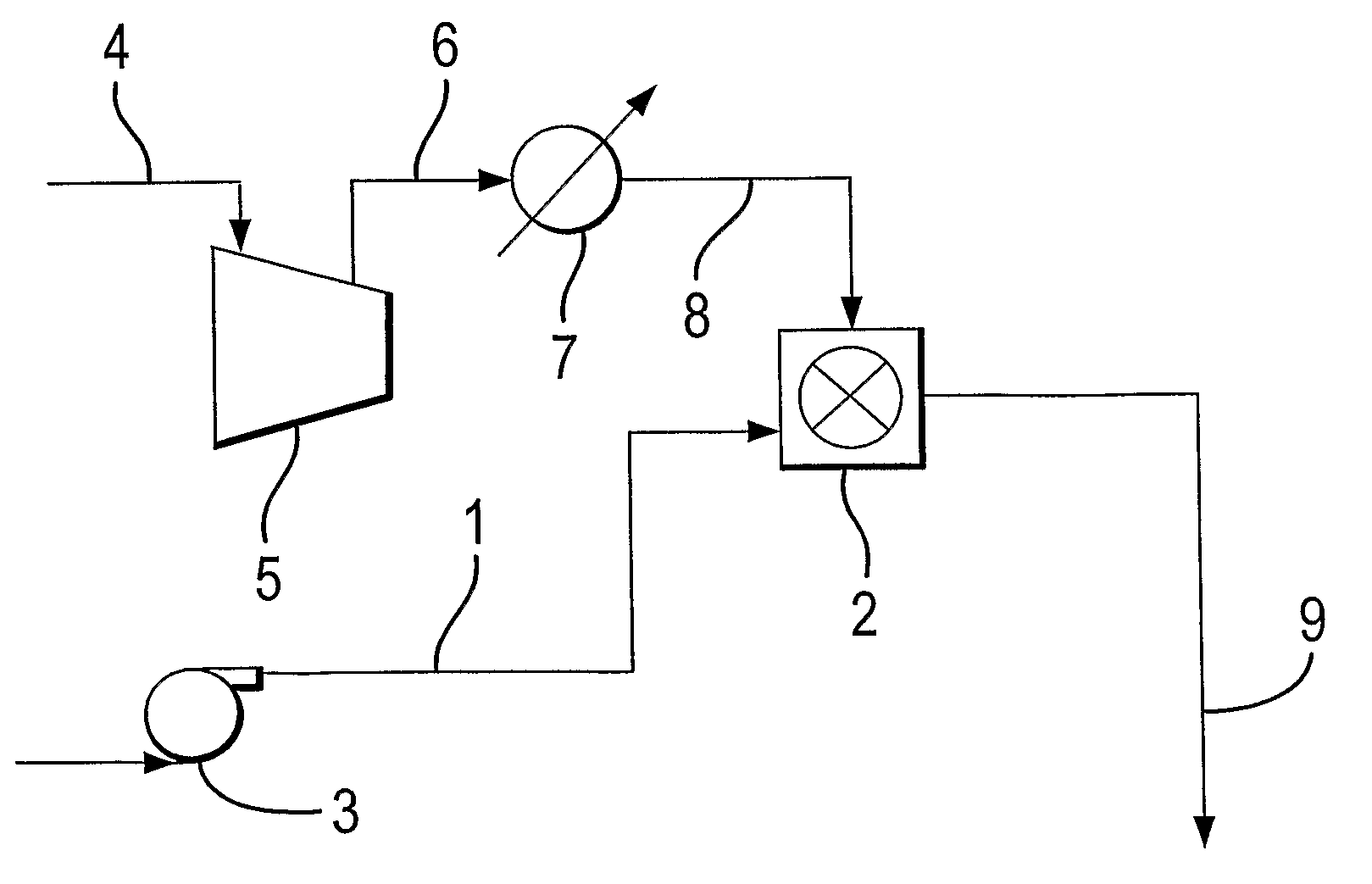
[0066]FIG. 1 illustrates a phase diagram for a generic multi-component composition.

[0067]The region inside the phase diagram is two phase. The region to the left of the phase diagram is liquid, the region to the right of the phase diagram is vapour, the region inside the phase diagram is two phase, and the region above the phase diagram (above the cricondenbar) is dense phase.

[0068]The “cricondenbar” for a multi-component composition is the highest pressure at which two phases can coexist. Thus, where the pressure is above the cricondenbar, a multi-component composition cannot be two-phase (both liquid and vapour).

[0069]The “cricondentherm” for a multi-component composition is the highest temperature at which two phases can co-exist.

[0070]The “critical point” for a multi-component composition is an experimentally determinable point and is the point (temperature and pressure) on the phase diagram where the mixture properties in the vapour phase and the liquid phase are the same.

[0071...


PUM


Abstract

A method of storing CO2 in a porous and permeable hydrocarbon reservoir having at least one injection well and at least one production well penetrating the reservoir, by recovering a produced fluid stream including produced hydrocarbons, produced water, and produced CO2 from the production well; passing the produced fluid stream to a production facility where a produced vapor stream of carbon dioxide and volatile hydrocarbons is separated from the produced fluid stream; compressing the produced vapor stream to above the cricondenbar for the produced vapor stream; cooling the compressed stream to form a cooled stream that in a dense phase state; importing a CO2 stream to an injection facility wherein the imported CO2 is either in a liquid state or a supercritical state; mixing the cooled stream with the imported CO2 stream thereby forming a co-injection stream; and injecting the co-injection stream into the hydrocarbon bearing reservoir from said injection well.

Description

[0001]This application is the U.S. national phase of International Application No. PCT / GB2008 / 003684, filed 30 Oct. 2008, which designated the U.S. and claims priority to European Application No. 07254378.8, filed 6 Nov. 2007, the entire contents of each of which are hereby incorporated by reference.[0002]The present invention relates to storage of carbon dioxide (CO2) in a porous and permeable subterranean reservoir, and, in particular, to the injection of CO2 into a hydrocarbon reservoir for storage of the CO2 therein.BACKGROUND OF THE INVENTION[0003]CO2 is a gas produced as a by-product, in large quantities, in certain industrial operations, e.g. the manufacture of ammonia, in power plants that burn fossil fuels such as coal, oil or gas, and in a hydrogen plant that produces hydrogen by reforming of a hydrocarbon feedstock. Release of this by-product into the atmosphere is undesirable as it is a greenhouse gas. Much effort has been made towards the development of methods for the ...

Claims


Application Information

Patent Timeline
Patent Type & Authority Patents(United States)
IPC IPC(8): E21B43/16
CPCY02E60/322E21B43/164Y02C10/14Y02P90/70Y02C20/40E21B41/0064
Inventor COLLINS, IAN RALPHMASON, ANDREW RUSSELL
Owner BP EXPLORATION OPERATING CO LTD
Why Eureka
Try Eureka