Apparatus for scribing thin films in photovoltaic cells

Active Publication Date: 2014-01-07
VINYL TECH
View PDF17 Cites 1 Cited by
  • Summary
  • Abstract
  • Description
  • Claims
  • Application Information

AI Technical Summary

Benefits of technology

[0017]The long-standing but heretofore unfulfilled need for an apparatus that improves the scribing process by reducing the need for large overlapping of c

Problems solved by technology

The price of the optic increases with increasing complexity of the focusing objective.
The laser energy absorbed prior to ablation threshold goes into the material as heat, causing thermal damage to the thin film and surrounding area.
This large overlaps slows down the scribing process considerably.
However, homogenization is difficult to implement for scribing applications because the optics used in such scribing systems tend to be flying optics; this precludes using imaging-based homogenized laser beams.
However, such devices cannot tolerate variation to the input laser beam or beam misalignment.
Accordingly, they have not found much use in production systems.
Focused laser beams that are predominately Gaussian or Gaussian-like in shape are not ideal where a steep energy transiti

Method used


Image

  • Apparatus for scribing thin films in photovoltaic cells
  • Apparatus for scribing thin films in photovoltaic cells
  • Apparatus for scribing thin films in photovoltaic cells

Examples


Example

[0064]This is accomplished in a first embodiment of the invention by making a special telescope 10 that includes an array of four (4) spherical lenses as depicted in FIGS. 2A, 2B, and 2C. The spherical lenses, denoted 12, 14, 16, 18, are cut as square elements and placed side by side. The telescope is a Keplerian type with 1× magnification so as not to alter the outer dimension of the beam.

[0065]FIG. 2A depicts the telescope in side elevation, FIG. 2B provides a top plan view, and FIG. 2C is an end view thereof. Although the 4×4 Keplerian telescope would in theory produce the desired inverted Gaussian beam, it is difficult to manufacture the lenses with enough accuracy to avoid aberrations and asymmetry in the inverted Gaussian profile. The lenses add power to the beam and alignment for collimation is paramount for good functionality.

Example

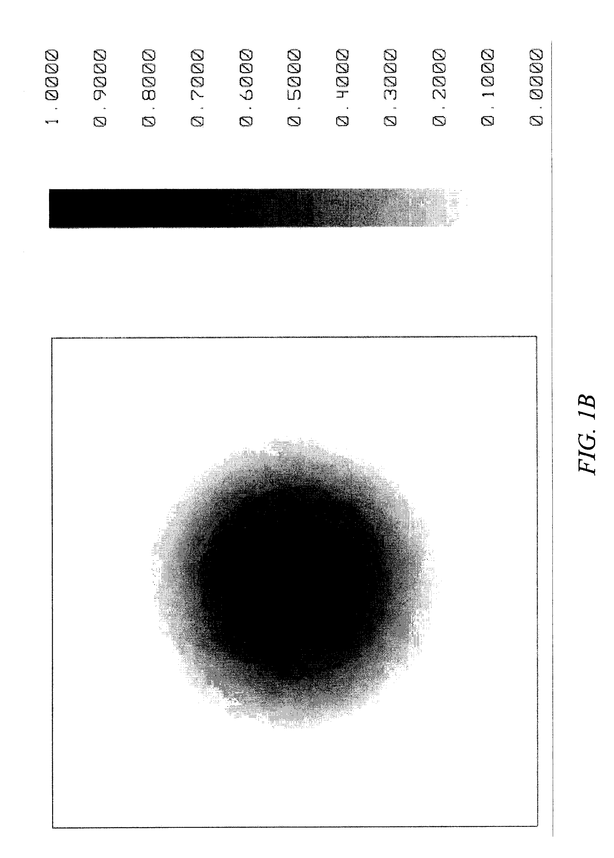
[0066]FIGS. 3A and 3B depict a second embodiment in side and top plan elevation, respectively, where a cube of glass 20 is rotated forty five degrees (45°) on either an X axis or Y axis, assuming the optical axis of the laser light propagates along the Z axis. A single cube of glass inverts the laser beam in one axis and this alone is sufficient for scribing in one axis of a solar panel with good results. FIG. 3C depicts the beam pattern, as a cross-sectional view grey scale intensity profile, produced by this apparatus.

Example

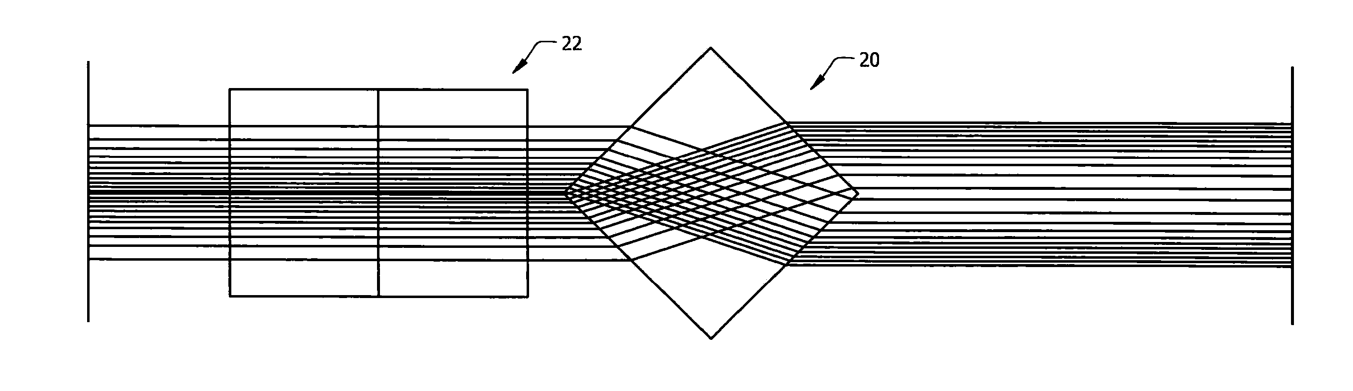
[0067]FIGS. 4A and 4B depict a third embodiment in side and top plan elevation, respectively, where a second cube of glass 22 is added and equally rotated forty five degrees (45°) about the X axis of the first rotated prism 10 and then further rotated ninety (90°) about the Z (optical) axis to invert in both axes. The beam pattern produced by this apparatus is depicted in FIG. 4C.

[0068]The preferred embodiment is a single piece of glass such as an octahedron optical element 24 depicted in FIG. 5A that inverts both axes of the Gaussian beam as depicted in FIG. 5B. Each surface of the polygon refractor is coated to minimize surface reflection losses with a suitable anti-reflection coating for the laser wavelength being used for scribing. Each octahedron has eight inclined, triangular sides.

[0069]The grey scale intensity profile of the apparatus depicted in FIGS. 5A and 5B is depicted in FIG. 1D.

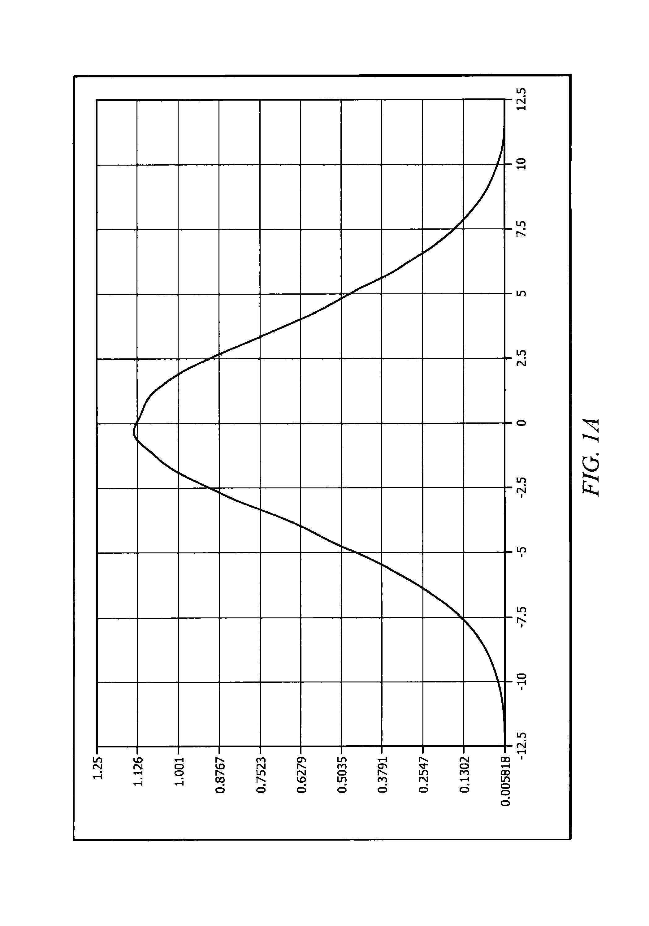
[0070]FIG. 6 graphically depicts a cross sectional intensity profile of a focused spot of l...


PUM

PropertyMeasurementUnit
Angleaaaaaaaaaa
Angleaaaaaaaaaa
Energyaaaaaaaaaa

Abstract

A thin-film scribing apparatus employing an optical device converts a low M2, Gaussian or pseudo-Gaussian beam into an inverted Gaussian beam. The all refractive optical device is such that it is not susceptible to either beam size or angular variations and exhibits very little loss of energy for the transformation process. The output can be configured for either single or dual-axis operation where the geometric shape of the beam is rectangular or square with steep edge intensity. The resulting rectangular beam requires less beam overlap and has very little shoulder in the intensity profile, providing high uniformity scribe features with greatly improved processing speeds.

Description

BACKGROUND OF THE INVENTION[0001]1. Field of the Invention[0002]This invention relates, generally, to optics. More particularly, it relates to scribing thin films in photovoltaic cells.[0003]2. Description of the Prior Art[0004]Conventional scribing of thin films used in solar cells uses focused Gaussian or Gaussian-like laser beams. A round Gaussian laser beam is passed through a focusing lens. Typically, a singlet, best form lens, or a doublet is used, depending upon how tightly the user wants to focus. The price of the optic increases with increasing complexity of the focusing objective.[0005]The substrate to be scribed is placed at the focus of the lens. Thin films ablate from the substrate after the intensity of the focused laser beam reaches a particular threshold. The laser energy absorbed prior to ablation threshold goes into the material as heat, causing thermal damage to the thin film and surrounding area.[0006]Moreover, laser beams are predominately round. Accordingly, a ...

Claims


Application Information

Patent Timeline
IPC IPC(8): B23K26/00B23K26/08B23K26/06B23K26/36
CPCB23K26/0823B23K26/365B23K26/0656B23K26/367B23K26/0652G02B27/0927B23K26/364
Inventor SCAGGS, MICHAEL, J.
Owner VINYL TECH
Why Eureka
Try Eureka