Delivery of electric power by means of a plurality of parallel inverters and control method based on maximum power point tracking

a technology of electric power delivery and parallel inverter, which is applied in the direction of electric variable regulation, process and machine control, instruments, etc., can solve the problems of inverter entail at worst a reduction in power delivered but not stoppage of delivery, all the energy produced until the repair of the inverter is lost, and the inverter can entail at worst a reduction in power delivered, so as to achieve greater efficiency in the extraction of electric power

Active Publication Date: 2014-01-07
MARICI HLDG THE NETHERLANDS BV
View PDF9 Cites 7 Cited by
  • Summary
  • Abstract
  • Description
  • Claims
  • Application Information

AI Technical Summary

Benefits of technology

[0016]One object of the present invention is to provide a method for controlling or managing an electric power generation system, comprising at least one direct current source that delivers an electric power subject to fluctuations, which makes it possible to achieve greater efficiency in extraction of the electric power from said source.
[0020]Unlike some traditional techniques, the inverters operate at variable power, tracking—via the MPPT algorithm performed by one of said inverters—the maximum power point corresponding to the condition of the system at that moment. This ensures very rapid system adaptation to variable operating conditions. For example, if the power source comprises one or more photovoltaic panels, the system thus controlled tracks very efficiently and rapidly the maximum power point on the power-voltage curve, maximizing the extraction of available power.
[0023]In an improved embodiment of the invention, the number of active inverters connected in parallel at the output of said direct current source can be varied over time, in order to minimize the number of inverters active and optimize the output of each inverter, according to the maximum theoretical power that can be delivered by said source according to the weather.

Problems solved by technology

When the power supplied by the alternative source is insufficient to power the load, it is powered wholly or partly by power taken from the grid.
Secondly, they must ensure that the converter output current is in phase with the grid voltage.
These systems have the drawback that if the inverter fails, all the energy produced until repair of the inverter is lost.
If the system is not connected to the grid but is the sole source of electricity for a given utility, inverter failure means that no electricity is supplied to said utility, with obvious and possibly serious inconveniences.
In these systems the failure of an inverter can entail at worst a reduction in the power delivered but not stoppage of the delivery, thanks to the redundancy provided by the plurality of inverters in parallel.
This, system has the drawback of involving a high cost due to the presence of a large number of switches which, in addition to being subject to failure, require a relatively complex control system for commutation.
This way of managing the modular system has one substantial drawback, however: impossibility of prompt adaptation to variation in the conditions of sunlight, i.e. variation of the power radiated by the sun and collected by the photovoltaic panels.
In reality, when the sun is obscured by clouds, the amount of power radiated is unpredictably and significantly modified.
When the power radiated is suddenly reduced by the passage of a cloud, the system described in U.S. Pat. No. 6,285,572 requires a relatively long time to re-identify, via execution of the MPPT algorithm, the operating point that permits extraction of the maximum power from the panel towards the grid.
This known system is not able to adequately manage these transients, consequently resulting in a substantial loss of power, since the output voltage of the photovoltaic panels cannot be promptly brought to the optimal value in any sunlight condition, i.e. to the value that permits extraction of maximum power from the panels.

Method used


Image

  • Delivery of electric power by means of a plurality of parallel inverters and control method based on maximum power point tracking
  • Delivery of electric power by means of a plurality of parallel inverters and control method based on maximum power point tracking
  • Delivery of electric power by means of a plurality of parallel inverters and control method based on maximum power point tracking

Examples


Embodiment Construction

[0034]Here below the present invention will be described with specific reference to an application to a system of photovoltaic panels for exploitation of solar energy, but the principles underlying the invention can also be used in systems based on other renewable energy sources.

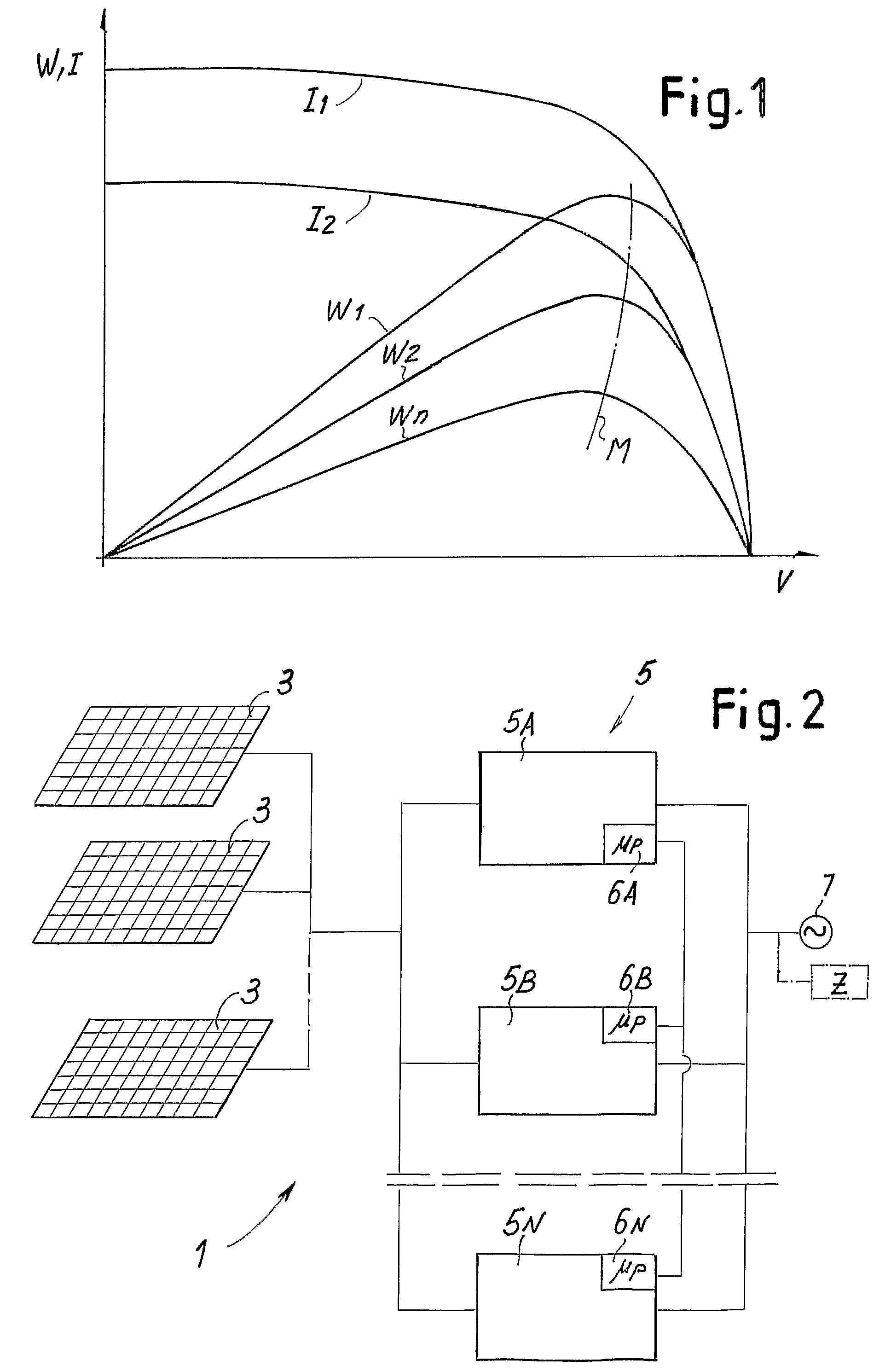
[0035]FIG. 1 shows the characteristic current and power curves according to the voltage at the output of the photovoltaic panel, already referred to in the introduction of the present description.

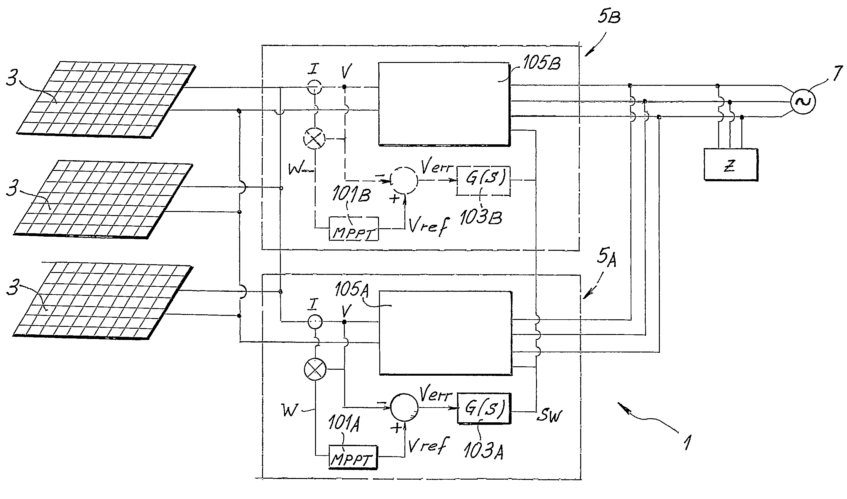
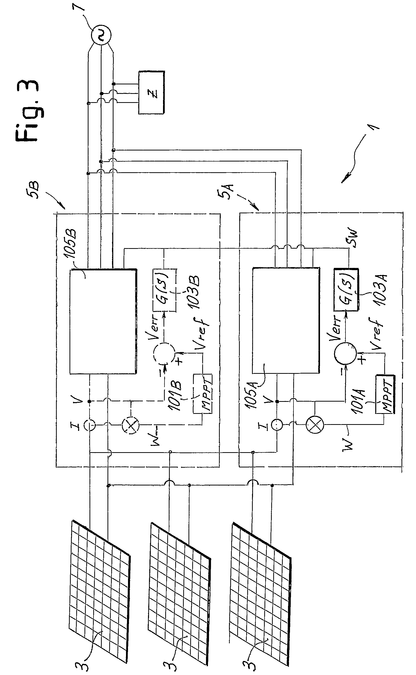
[0036]FIG. 2 very schematically shows a plant or system 1 for generation of electricity via the use of a series of photovoltaic panels 3. The photovoltaic panels 3 are connected to a plurality of inverters indicated overall by 5 and individually indicated by 5A, 5B . . . 5N. The inverters 5, each of which is provided with a control unit 6A, 6B . . . 6N, are interconnected in parallel and the outputs are connected to a grid 7, schematized as an ideal voltage generator. The inverters can also be connected to a local l...


PUM


Abstract

The system provides for one or more photovoltaic panels (3) or other energy sources, connected to a series of inverters (5) in parallel, the outputs of which are connected to a load (Z) and / or to an electricity distribution grid (7). One of the inverters operates as master unit and generates a power control signal in order to track the maximum power point that can be obtained from the panels (3). The other inverters operate as slave units. The control is performed so that all the inverters absorb a variable quantity of power according to the fluctuations in the power available at the output of the photovoltaic panels (3) or other source subject to fluctuations.

Description

TECHNICAL FIELD[0001]The present invention concerns improvements to the systems for production of electricity from renewable sources, for example (but not exclusively) photovoltaic panels or other sources subject to fluctuation in the power delivered. In particular, the present invention concerns improvements to the methods and devices for controlling systems for the production of electricity having the function of maximizing the extraction of polder.STATE OF THE ART[0002]To tackle the problem of environmental pollution and the growing demand for electricity also for domestic use, the installation of distributed electricity generator units is currently being promoted for the supply of medium-sized loads, for example in housing and commercial facilities or in industrial environments. These generator units use alternative energy, and in particular renewable sources such as solar energy, via photovoltaic, cells forming panels or so-called photovoltaic arrays, or wind energy by means of...

Claims


Application Information

Patent Timeline
Patent Type & Authority Patents(United States)
IPC IPC(8): H02J3/00
CPCY02E10/58H02M7/493G05F1/67Y10T307/707H02J2300/26H02J3/381Y02E10/56H02J3/46
Inventor MARCIANESI, ANDREAMARTINI, DAVIDSOLDANI, SIMONE
Owner MARICI HLDG THE NETHERLANDS BV
Why Eureka
Try Eureka