Vertebral body replacement and method of use

a technology of vertebral body and vertebrae, which is applied in the field of vertebral body replacement and method of use, can solve the problems of back pain, economic cost, alone exceeding $80 billion annually, etc., and achieve the effects of simple geometry, easy insertion into intervertebral space, and simple geometry

Inactive Publication Date: 2014-01-14
MUHANNA NABIL L M D
View PDF60 Cites 5 Cited by
  • Summary
  • Abstract
  • Description
  • Claims
  • Application Information

AI Technical Summary

Benefits of technology

[0017]There is a need for a vertebral body replacement having a simple geometry that can be easily inserted into an intervertebral space while causing minimal trauma to the surface of the vertebrae as well as the bony processes thereof. The present invention provides a vertebral body replacement having a simple geometry for supporting adjacent vertebrae after excision, at least partially or wholly, of an intervertebral disc. The body replacement includes a body having a lower surface and an upper surface. The lower surface will be supported by a lower vertebra; the upper surface will support the adjacent upper vertebra. The body of the vertebral body replacement of the present invention, therefore, provides support between the two adjacent vertebrae and to the spinal column.
[0018]The body of the vertebral body replacement of the present invention additionally has an anterior face and a posterior face extending from the lower surface. The height of the anterior face of the body may be greater than the height of the posterior face to maintain the curvature of the spine when the vertebral body replacement is inserted between two vertebrae. A stabilizing body is connected to and extends from the body of the body replacement. The stabilizing body may be connected to the body of the body replacement by an attachment member that optionally allows the body and the stabilizing body to rotate relative to each other. The present invention further provides a vertebral body replacement having a locking assembly whereby the body and the stabilizing body, once orientated to a desired position with a spinal column, and relative to each other, may be rigidly locked.
[0021]The present invention further provides a method of maintaining a separation distance between adjacent vertebrae. At least one vertebral body replacement according to the present invention can be inserted into an intervertebral space to support the adjacent vertebrae. The body of the vertebral body replacement may be inserted into the receiving intervertebral space in an orientation that reduces contact between the body replacement and the adjacent vertebrae. Once inserted into the selected position, the body of the vertebral body replacement may be rotated so that the lower surface and the upper surface of the body contact the adjacent vertebrae, whereupon the body is secured by attaching (if necessary) and locking the stabilizing body.
[0022]In another embodiment, a vertebral body replacement is provided having a shape resembling, in part, a bullet, football, or other oblong object. The vertebral body replacement of this embodiment includes a front end in a nose shape to provide a minimally invasive installation, serrations formed in the wall of the body replacement's body to prevent expulsion once the body replacement is in place, and a tapered asymmetric shape to provide spinal lordosis. The vertebral body replacement of this embodiment is typically used in pairs by placing flat faces of adjacent vertebral body replacements in planes parallel to and in near contact with one another. The vertebral body replacement of this embodiment also includes a threaded hole for assembly tooling, an integral protrusion to provide stability, and two window shaped passages extending generally from top to bottom through the body that are typically filled with bone tissue. The integral protrusion, in an exemplary embodiment, defines an arcuate face which appears as a “bloated” or bulbous protrusion and is formed to provide stability in the horizontal plane and prevents tilting or rotation within the plane. The integral stabilizing protrusion also acts to increase the bearing area to reduce contact pressure between the body replacement and the vertebral plate. The body is also provided with holes passing completely through the body, from side to side, to promote tissue growth.
[0023]In yet another embodiment, a vertebral body replacement is provided having a shape resembling, in part, a bullet, football, or other oblong object. The vertebral body replacement of this embodiment includes a front end in a nose shape to provide a minimally invasive installation, serrations formed in the wall of the body replacement's body to prevent expulsion once the body replacement is in place, and a tapered asymmetric shape to provide spinal lordosis. The vertebral body replacements of this embodiment are typically used in pairs by placing flat faces of adjacent vertebral body replacements in planes parallel to and in near contact with one another. The vertebral body replacement of this embodiment also includes a threaded hole for assembly tooling, two growth hole faces that are both flat, and two window shaped passages extending generally from top to bottom through the body that are typically filled with bone tissue. The body is also provided with holes passing completely through the body, from flat face to flat face, to promote tissue growth.

Problems solved by technology

Back pain is one of the most significant problems facing the workforce in the United States today.
It is a leading cause of sickness-related absenteeism and is the main cause of disability for people aged between 19 and 45.
Published reports suggest that the economic cost is significant, treatment alone exceeding $80 billion annually.
The most common cause of disabling back pain, however, stems from trauma to a intervertebral disc, resulting from mechanical shock, stress, tumors or degenerative disease, which may impair functioning of the disc and limit spinal mobility.
In many cases, the disc is permanently damaged and the preferred treatment becomes partial or total excision.
Another cause of back injury is herniation of the intervertebral disc, wherein the gelatinous fluid of the nucleus pulposus enters the vertebral canal and pressures the spinal cord.
Traumatic injury to an intervertebral disc that is not removed will frequently promote scar tissue formation.
Scar tissue is weaker than original healthy tissue so that the disc will progressively degenerate, lose water content, stiffen and become less effective as a shock absorber.
Eventually, the disc may deform, herniate, or collapse, limiting flexibility of the spinal column at that position.
However, mechanical devices intended to replicate intervertebral disc function have had only limited success.
The disadvantage of such body replacements is that stability is created at the expense of the flexibility of the spine.
The excess removal of the bony process triggers further degradation and impediment of the normal movement of the spine.
The anterior approach to the spinal column is complicated by the internal organs that must be bypassed or circumvented to access the vertebrae.
Many intervertebral body replacements require preparation of the surfaces of the adjacent vertebrae to accommodate the body replacement, causing significant tissue and bone trauma.
They may also require screwing the body replacement into the intervertebral space, making installation difficult and increasing trauma to the vertebral tissue.
Many body replacements include complex geometries and are costly to manufacture.
Many of these complex body replacements may require screwing the body replacement into the intervertebral space, thereby making installation difficult and traumatic to the vertebral tissue.

Method used


Image

  • Vertebral body replacement and method of use
  • Vertebral body replacement and method of use
  • Vertebral body replacement and method of use

Examples


Embodiment Construction

[0056]A full and enabling disclosure of the present invention, including the best mode known to the inventor of carrying out the invention, is set forth more particularly in the remainder of the specification, including reference to the accompanying drawings, wherein like reference numerals designate corresponding parts throughout several figures. This description is made for the purpose of illustrating the general principles of the invention and should not be taken in the limiting sense.

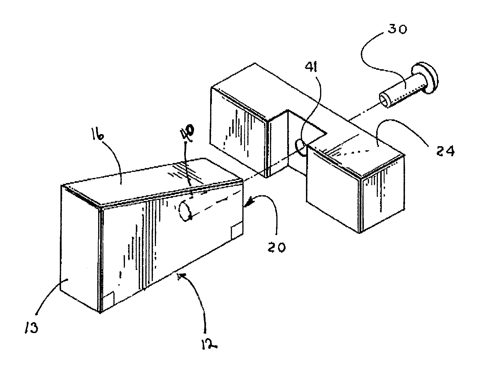
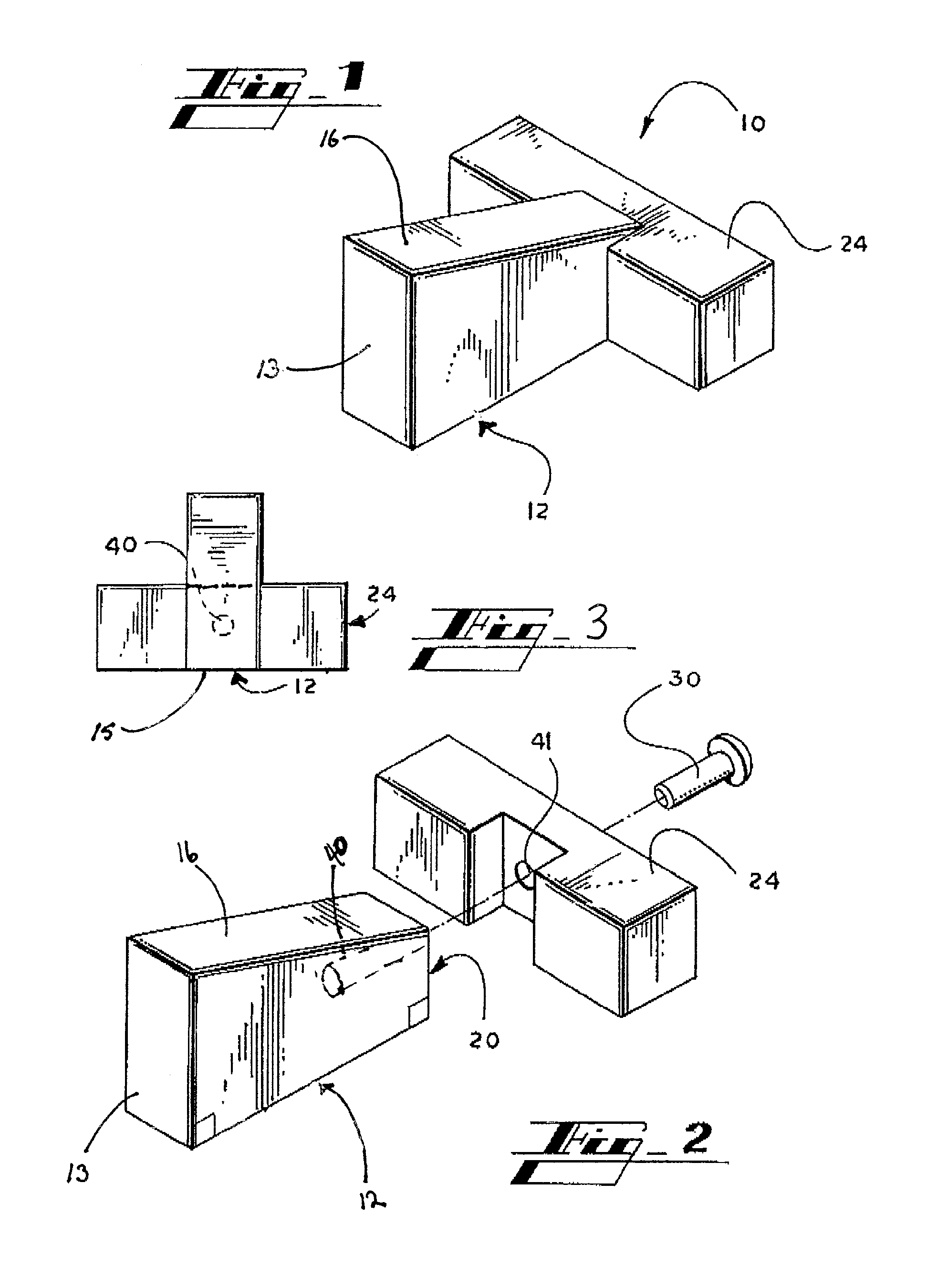
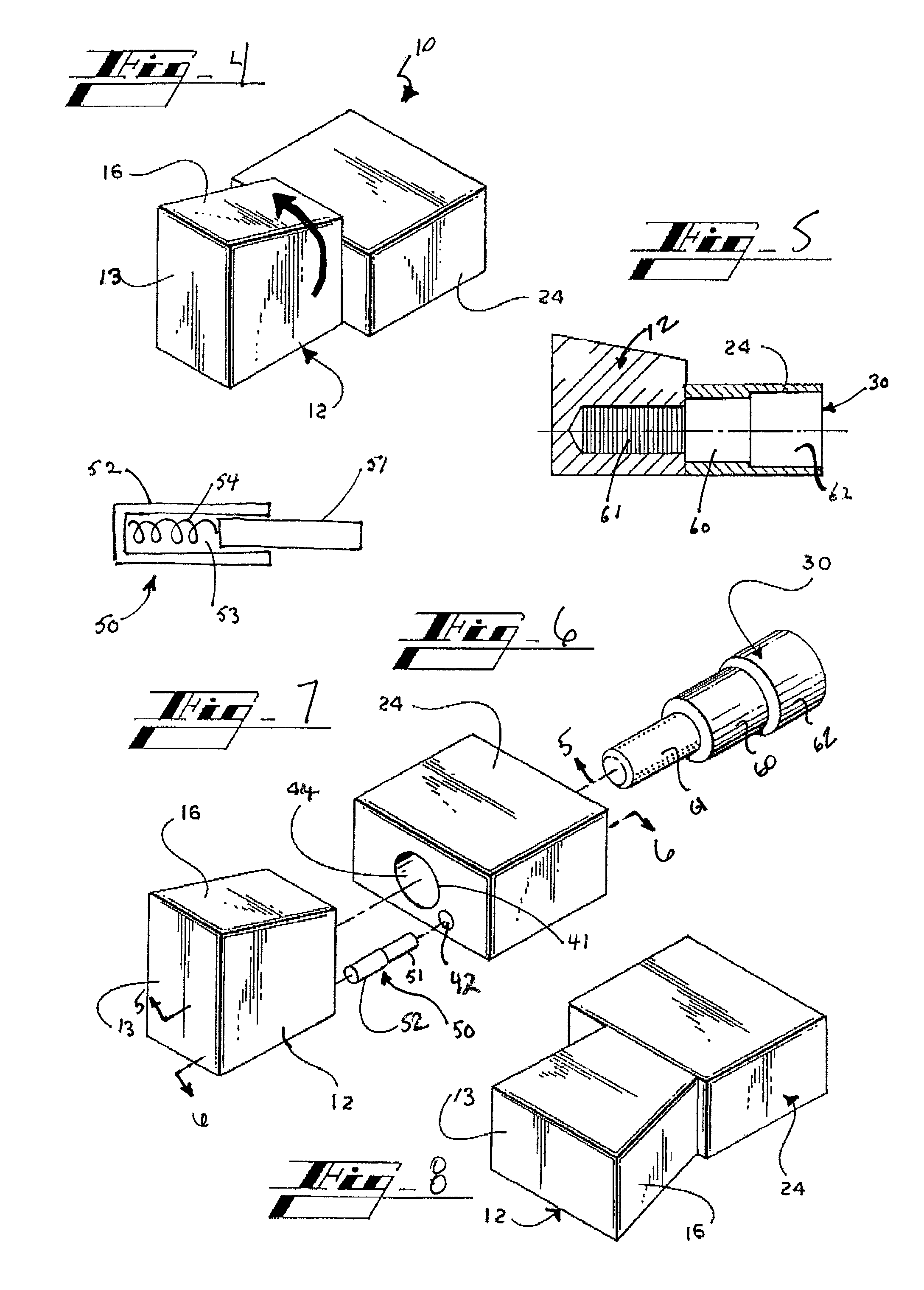
[0057]Examples of the vertebral body replacement 10 in accordance with the present invention are shown in FIGS. 1-20. As shown in FIG. 22, the vertebral body replacements 10 of the present invention support adjacent vertebrae 20 after partial or total surgical excision of an intervertebral disc 21, thereby preventing collapse and / or compression in this region of the spine that might otherwise lead to sever neurological damage. The vertebral body replacement 10 of the present invention is useful to r...


PUM


Abstract

Vertebral body replacements are provided, including at least one vertebral body replacement in the shape of an oblong object. The oblong vertebral body replacement includes a nose shape to provide as minimally invasive an installation as possible, serrations formed in the side wall of the body replacement's body to prevent expulsion once the body replacement is in place, a tapered asymmetric shape to provide spinal lordosis, and an integral protrusion for stability and to increase the bearing area to reduce contact pressure between the body replacement and the vertebral plate. Hollow passages are typically filled with bone tissue. The body is also provided with holes passing therethrough to promote tissue growth.

Description

CROSS-REFERENCE TO RELATED APPLICATIONS[0001]This application is a continuation of application Ser. No. 10 / 701,883, filed on Nov. 5, 2003; now abandoned which application is a continuation-in-part of application Ser. No. 09 / 941,040, filed Aug. 28, 2001; now abandoned which claims the benefit of provisional application No. 60 / 228,694, filed Aug. 29, 2000.[0002]Application Ser. No. 10 / 701,883 is also a continuation-in-part of application Ser. No. 09 / 947,851, filed Sep. 6, 2001, now U.S. Pat. No. 6,824,565; which claims the benefit of provisional application No. 60 / 231,142, filed Sep. 8, 2000.[0003]Application Ser. No. 10 / 701,883 also claims the benefit of provisional application No. 60 / 476,075, filed Jun. 5, 2003, the entirety of which is incorporated herein by reference.INCORPORATION BY REFERENCE[0004]The specification of application Ser. Nos. 10 / 701,883, 09 / 947,851, published under 20020045944; application Ser. No. 10 / 403,598, published under no. 20030171814; and application Ser. No...

Claims


Application Information

Patent Timeline
Patent Type & Authority Patents(United States)
IPC IPC(8): A61F2/44
CPCA61F2002/30787A61F2002/30285A61F2/4611A61F2002/4629A61F2002/4475A61F2002/4631A61F2/4455A61F2/4465A61F2002/30593
Inventor MUHANNA, NABIL L.SCHALLIOL, DAVID L.
Owner MUHANNA NABIL L M D
Why Eureka
Try Eureka