Electro-conductive member, process cartridge, and electrophotographic apparatus

a technology of electrophotography and electro-conductive components, applied in the direction of electrographic processes, instruments, corona discharge, etc., can solve the problems of pinhole leakage, portion that cannot be charged, and excessive resistance reduction of electro-conductive components in the h/h environment, so as to reduce resistance value under the l/l environment, the effect of optimizing the resistance valu

Active Publication Date: 2014-01-14
CANON KK
View PDF10 Cites 34 Cited by
  • Summary
  • Abstract
  • Description
  • Claims
  • Application Information

AI Technical Summary

Benefits of technology

[0016]In view of the foregoing, the present invention is directed to providing an electro-conductive member for electrophotography showing a stable resistance value under various use environments. Further, the present invention is directed to providing a process cartridge and an electrophotographic apparatus capable of stably providing high-quality electrophotographic images over a long time period.
[0019]According to the present invention, the excessive reduction in resistance of an electro-conductive member under the H / H environment can be suppressed, and at the same time, the resistance value under the L / L environment can be reduced. As a result, the resistance value can be optimized without depending on the use conditions and the use environment, and an electro-conductive member in which contamination of a photosensitive member is suppressed can be obtained. Further, according to the present invention, provided are the process cartridge and the electrophotographic apparatus capable of providing high-quality electrophotographic images.

Problems solved by technology

In the case of a charging roller that is placed so as to abut on a photosensitive drum in an electrophotographic apparatus and charges the photosensitive drum as an example of the electro-conductive member, when the resistance increases under the L / L environment, a charging failure may occur.
In addition, an excessive reduction in resistance under the H / H environment may cause a pinhole leak.
When the photosensitive layer of the photosensitive drum has a faulty site, an excessive current converges from the charging roller to the faulty site, and hence a portion that cannot be charged occurs around the faulty site of the photosensitive layer.
In addition, when an ionic electro-conductive charging roller is used in an AC / DC charging system as a system involving applying a voltage obtained by superimposing an alternating-current voltage (AC voltage) on a direct-current voltage (DC voltage) to the charging roller, a reduction in resistance of the ionic electro-conductive charging roller under the high-temperature, high-humidity environment causes an excessive amount of a discharge current.
As a result, the rate at which the photosensitive drum deteriorates is remarkably large as compared with that in the DC charging system, thereby shortening the lifetime of the photosensitive drum.
Further, such rate causes image deletion as an image failure resulting from a discharge product such as a nitrogen oxide.
It has been difficult to solve the problems in the AC / DC charging system while suppressing the occurrence of such sandy image.
Particularly under the high-temperature, high-humidity environment, a discharge current amount needed for suppressing the sandy image has become excessive owing to the reduction of the resistance of the ionic electro-conductive charging roller in some cases.
In the case of a developing roller, which is used as a toner carrying member upon visualization of an electrostatic latent image formed on a photosensitive member as a toner image in an electrophotographic apparatus, as another example of the electro-conductive roller as well, an increase and excessive reduction in resistance value lead to challenges.
When the resistance of the developing roller increases under the L / L environment, charges accumulated on the developing roller may become unlikely to be discharged.
As a result, there may occur a “fogging” image, in which toner is developed in a portion other than an image portion.
On the other hand, when the resistance of the developing roller excessively reduces under the H / H environment, the pinhole leak may occur as in the case of the charging roller.

Method used


Image

  • Electro-conductive member, process cartridge, and electrophotographic apparatus
  • Electro-conductive member, process cartridge, and electrophotographic apparatus
  • Electro-conductive member, process cartridge, and electrophotographic apparatus

Examples


production example 1

Production of Elastic Roller

[0131]An elastic roller was produced according to the following procedure.

[0132]

[0133]An “A-kneading rubber composition 1” was obtained by mixing respective materials whose kinds and amounts were shown in Table 1 below with a pressure kneader. Further, the respective materials whose kinds and amounts were shown in Table 2 below were mixed into 177 parts by mass of the A-kneading rubber composition with an open roll. Thus, an “unvulcanized rubber composition 1” was prepared.

[0134]

TABLE 1Blending amountMaterial(part(s) by mass)Raw rubberNBR (trade name: Nipol100DN219, manufactured byZEON CORPORATION)Electro-Carbon black40conductive agent(trade name: TOKABLACK#7360SB, manufactured byTOKAI CARBON CO., LTD.)FillerCalcium carbonate20(trade name: Nanox #30,manufactured by MARUOCALCIUM CO., LTD.VulcanizationZinc oxide5accelerating aidProcessing aidStearic acid1

[0135]

TABLE 2Blending amountMaterial(part(s) by mass)CrosslinkingSulfur1.2agentVulcanizationTetrabenzylt...

production example 2

Preparation of Coating Liquid

[0139]A coating liquid containing a binder resin for forming the electro-conductive layer according to the present invention was prepared according to the following procedure. It should be noted that the binder resin of the present invention is produced from: an ionic electro-conductive agent (I) having a reactive functional group as a raw material; a carrier molecule (II) which is a counter ion of the ionic electro-conductive agent; and a binder resin (III) as a raw material.

[0140]

[0141]8.56 Grams (56.5 mmol) of glycidyltrimethylammonium chloride as an ionic electro-conductive agent (I) having a reactive functional group were dissolved in 50 ml of purified water and then the solution was stirred for 1 hour. Next, 16.22 g (56.5 mmol) of lithium cyclohexafluoropropane-1,3-bis(sulfonyl)imide as a carrier molecule (II) which was a counter ion were dissolved in 50 ml of purified water and then the solution was stirred for 1 hour. Next, those two kinds of aqu...

example 1

1. Production of Electro-Conductive Roller 1

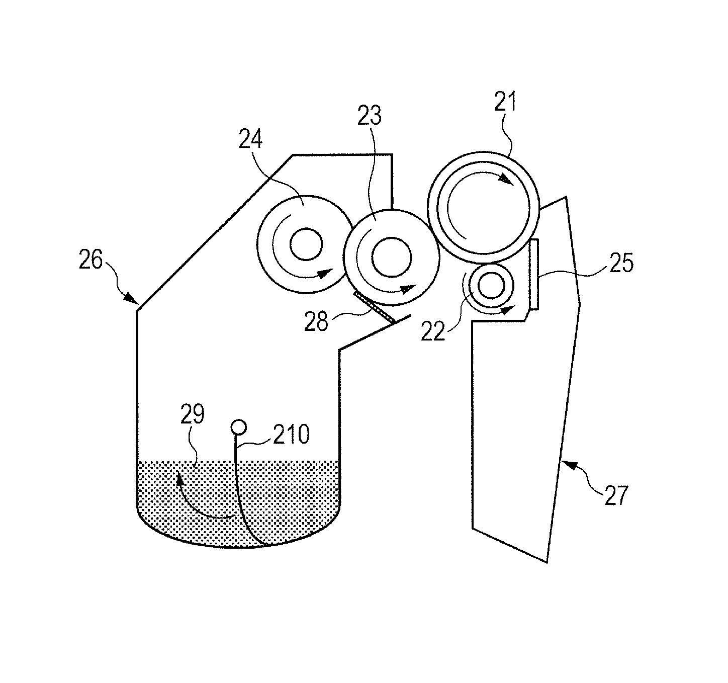
[0158]The elastic roller 1 obtained in Production Example 1 was coated with the coating liquid 1 obtained in Production Example 2 by a dipping method involving immersing the roller in the liquid with its longitudinal direction defined as a vertical direction. An immersion time was set to 9 seconds, an initial lifting speed was set to 20 mm / s, a final lifting speed was set to 2 mm / s, and a speed was linearly changed with time between the initial and final speeds. The resultant coated product was air-dried at 23° C. for 30 minutes. Next, the product was dried with a hot air-circulating dryer set to 90° C. for 1 hour. Further, the product was dried with a hot air-circulating dryer set to 160° C. for 3 hours. Thus, an electro-conductive layer was formed on the outer peripheral surface of the elastic roller 1. As a result, a “electro-conductive roller 1” was produced.

2. Characteristic Evaluation

[0159]Next, the electro-conductive roller 1 was su...


PUM

PropertyMeasurementUnit
temperatureaaaaaaaaaa
resistanceaaaaaaaaaa

Abstract

To suppress an excessive reduction in resistance of an electro-conductive roller under an H / H environment and reduce a resistance value thereof under an L / L environment, provided is an electro-conductive member for electrophotography, comprising: an electro-conductive mandrel; and an electro-conductive layer provided on a periphery of the mandrel, wherein the electro-conductive layer contains a binder resin having an alkylene oxide structure, and a sulfo or a quaternary ammonium group as an ion exchange group, and an ion having polarity opposite to polarity of the ion exchange group, a water content of the electro-conductive layer under a temperature of 30° C. and a relative humidity of 80% is 10 mass % or less, and a spin-spin relaxation time of the electro-conductive layer, which is determined by pulse NMR measurement with a hydrogen core being a measurement core under a temperature of 15° C. and a relative humidity of 10%, is 200 μsec or more.

Description

CROSS-REFERENCE TO RELATED APPLICATIONS[0001]This application is a continuation of International Application No. PCT / JP2012 / 008201, filed Dec. 21, 2012, which claims the benefit of Japanese Patent Application No. 2011-284452, filed Dec. 26, 2011.BACKGROUND OF THE INVENTION[0002]1. Field of the Invention[0003]The present invention relates to an electro-conductive member, a process cartridge, and an electrophotographic apparatus.[0004]2. Description of the Related Art[0005]In an electrophotographic image-forming apparatus, an electro-conductive member has been used in various fields such as a charging roller, a developing roller, and a transfer roller. The resistance value of such electro-conductive member preferably falls within the range of 103 to 1010Ω. Accordingly, the conductivity of an electro-conductive layer which the electro-conductive member includes has been adjusted with an electro-conductive agent. Here, the electro-conductive agents are roughly classified into an electro...

Claims


Application Information

Patent Timeline
Patent Type & Authority Patents(United States)
IPC IPC(8): B32B27/34B32B27/36B32B27/18B32B27/40B32B27/38G03G15/02
CPCG03G15/00G03G15/08G03G15/02G03G15/16G03G5/14708G03G15/0233G03G15/1685G03G15/0818Y10T428/31725Y10T428/31786Y10T428/31663Y10T428/31511Y10T428/31551
Inventor YAMAUCHI, KAZUHIRONISHIOKA, SATORUWATANABE, MASAHIROKIKUCHI, YUICHIYAMADA, SATORUMURANAKA, NORIFUMI
Owner CANON KK
Why Eureka
Try Eureka