Wind turbine generator

a wind turbine generator and wind turbine technology, applied in the direction of marine propulsion, vessel construction, greenhouse gas reduction, etc., can solve the problems of increasing heat loss from the generator and heat loss from the hydraulic transmission, and achieve the effects of increasing the cross-sectional area simplifying the reinforcement of the duct part, and increasing the cross-sectional area

Inactive Publication Date: 2014-01-21
MITSUBISHI HEAVY IND LTD
View PDF36 Cites 13 Cited by
  • Summary
  • Abstract
  • Description
  • Claims
  • Application Information

AI Technical Summary

Benefits of technology

[0063]According to present invention, the inner wall of the nacelle forming the bottom surface of the duct part has the curved portion that curves inward toward the centerline of the nacelle with the increasing distance from the hub. By this, outward protrusion of the duct part is suppressed while the cross-sectional area of the duct part is increased from the intake port side to the exhaust port side. By suppressing the outward protrusion of the duct part, the force of the wind (the flow of the ambient air) acting on the duct part decreases, thereby simplifying reinforcement of the duct part. With the increased cross-sectional area of the duct part from the intake port side to the exhaust port side, the intake amount of the ambient air into the duct part increases due to the diffuser effect. As a result, the amount of heat the ambient air receives from the cooling medium is increased, and thus, the heat-producing component can be cooled effectively.

Problems solved by technology

With increased output of the generator produced by the larger wind turbine generator, heat loss from the generator increases.
In the wind turbine generator in which the rotation of the rotor is transmitted to the generator by a hydraulic transmission formed by a hydraulic pump and a hydraulic motor, in addition to the heat loss from the generator, there is heat loss from the hydraulic transmission.

Method used


Image

  • Wind turbine generator
  • Wind turbine generator
  • Wind turbine generator

Examples


first preferred embodiment

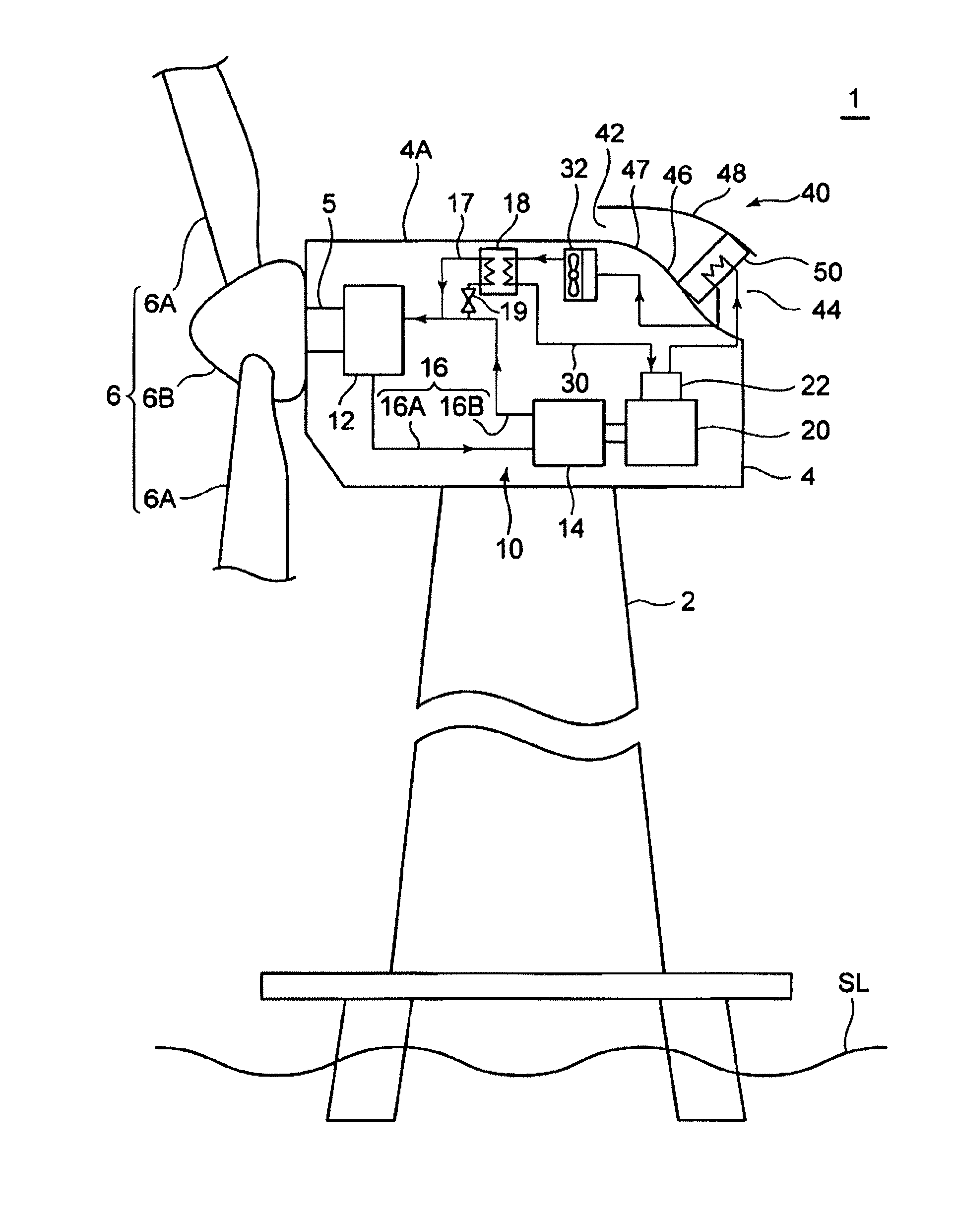
[0076]FIG. 1 shows an overall structure of a wind turbine generator in relation to a first preferred embodiment. FIG. 1 shows a wind turbine generator 1 which mainly includes a tower 2, a nacelle 4 supported to the tower 2 and a rotor 6 which rotates by wind power.

[0077]FIG. 1 shows the wind turbine generator 1 of an offshore type installed at the seal level (SL). However, the wind turbine generator 1 may be installed on shore.

[0078]The rotor 6 is formed by at least one blade 6A, e.g. three blades, and a hub 6B which supports the blade 6A. The hub 6B is connected to a main shaft 5 housed in the nacelle 4. By this, the wind acting on the blade 6A rotates the rotor 6, thereby rotating the main shaft 5 which is connected to the hub 6B.

[0079]A hydraulic transmission 10 and a generator 20 are housed in the nacelle 4. The hydraulic transmission 10 includes a hydraulic pump 12 connected to the main shaft 5, a hydraulic motor 14 connected to the generator 20 and an oil line 16 arranged betw...

second preferred embodiment

[0106]A wind turbine generator in relation to a second preferred embodiment is explained. The wind turbine generator of the second preferred embodiment has the same structure as the wind turbine generator 1 of the first preferred embodiment except for a fan additionally provided in the duct part 40 of the nacelle 4. Thus, the components that are already explained in the first preferred embodiment are indicated by the same reference numbers and are not explained further and mainly the structure different from the first preferred embodiment is explained here.

[0107]FIG. 5 shows a structure around the duct part 40 of the wind turbine generator in relation to the second preferred embodiment. FIG. 5 shows a fan 52 provided in the duct part 40 of the nacelle 4 in addition to the heat exchanger 50. By providing the fan 52 in the duct part 40, the intake amount of the ambient air into the duct part 40 is increased, thereby increasing the amount of heat the ambient air receives from the cooli...

third preferred embodiment

[0121]A wind turbine generator in relation to a third preferred embodiment is explained. The wind turbine generator of the third preferred embodiment has the same structure as the wind turbine generator 1 of the first preferred embodiment except for a shutter additionally provided in the duct part 40 of the nacelle 4. Thus, the components that are already explained in the first preferred embodiment are indicated by the same reference numbers and are not explained further and mainly the structure different from the first preferred embodiment is explained here.

[0122]FIG. 9 shows a structure around the duct part 40 of the wind turbine generator in relation to the third preferred embodiment. FIG. 9 shows a shutter 54 provided in the duct part 40 of the nacelle 4 in addition to the heat exchanger 50. As shown in FIG. 9, the shutter 54 may be constituted of a plurality of louver panels 55 arranged approximately parallel to one another and a frame supporting the louver panels 55. A variety...


PUM


Abstract

A wind turbine generator includes a tower, at least one blade, a hub supporting the blade, a nacelle supported by the tower and having a duct part with an intake port and an exhaust port, and a heat exchanger provided in the duct part and cooling a cooling medium for a heat-producing component inside the tower or nacelle. The wall of the nacelle has a double wall structure constituted of an inner wall and an outer wall in an area where the duct part is provided. The inner wall forms a bottom surface of the duct part and has a curved portion which curves inward toward a center line of the nacelle with increasing distance from the hub. The duct part increases in cross-section from a side of the intake port to a side of the exhaust port at least in an area where the curved portion is formed.

Description

RELATED APPLICATIONS[0001]The present application is continuation from PCT International Application of PCT / JP2011 / 068283 filed Aug. 10, 2011, the disclosure of which is hereby incorporated by reference herein in its entirety.TECHNICAL FIELD[0002]The present invention relates to a wind turbine generator equipped having a function of cooling a heat-producing component in a tower and a nacelle. The heat-producing component includes a generator, a hydraulic transmission, a transformer, a converter, a control board and the like.BACKGROUND ART[0003]From the perspective of preserving the global environment, wind turbine generators using renewable energy, i.e. wind power, are becoming popular. To improve power generation efficiency, it is desired to increase the size of the wind turbine generator. Particularly, wind turbine generators installed offshore are expensive to construct in comparison to those installed onshore and thus, it is desired to improve power generation efficiency by incr...

Claims


Application Information

Patent Timeline
Patent Type & Authority Patents(United States)
IPC IPC(8): F03D1/04
CPCY02E10/726F05B2260/20Y02E10/721F05B2240/12F03D11/00Y02E10/722F05B2240/14F03D9/28F03D80/60Y02E10/72Y02E70/30F05B2260/64F03D80/00
Inventor AKASHI, YUMATSUO, TAKESHISATO, SHINSUKEKAMEDA, TAKURO
Owner MITSUBISHI HEAVY IND LTD
Why Eureka
Try Eureka