Hydrogen gas production system utilizing silicon wastewater and method for production of hydrogen energy using the same

a technology of silicon wastewater and hydrogen gas, which is applied in the direction of process and machine control, instruments, and the nature of treatment water, etc., can solve the problems of clogging of uf membranes to be used for any further process, the recovery of production water from silicon wastewater and the recovery of production water is not enhanced to the desired level. , to achieve the effect of novel energy resources, improving the recovery of treated water, and reducing was

Active Publication Date: 2014-02-04
COWAY ENTECH CO LTD
View PDF7 Cites 1 Cited by
  • Summary
  • Abstract
  • Description
  • Claims
  • Application Information

AI Technical Summary

Benefits of technology

[0012]A still further object of the present invention is to provide a hydrogen energy production system utilizing silicon wastewater, which includes solidification of the residual waste remaining in the silicon wastewater, thus decreasing waste mass and efficiently reducing waste disposal costs, and a method for production of hydrogen energy using silicon wastewater by the foregoing system.
[0032]As described above, the present invention may perform secondary treatment of treated water obtained from silicon wastewater in order to reuse the finally treated water, thereby improving recovery of the treated water to a desired level.
[0034]In addition, the present invention may solidify the residual waste remaining in the silicon wastewater in order to decrease waste mass, thereby efficiently reducing waste disposal costs.

Problems solved by technology

However, the concentrated wastewater remaining after primary treatment of the silicon wastewater is excessively concentrated and causes abnormal conditions such as clogging of UF membranes to be used for any further process, for example, UF membrane filtration.
As a result, the conventional method entails a problem in that recovery of the production water from the silicon wastewater is not enhanced to a desired level.
Further, since the concentrated wastewater generated from the silicon wastewater is discarded without treatment, there may incur a high relatively disposal cost amounting to from 60,000 to 80,000 won per ton.

Method used


Image

  • Hydrogen gas production system utilizing silicon wastewater and method for production of hydrogen energy using the same
  • Hydrogen gas production system utilizing silicon wastewater and method for production of hydrogen energy using the same
  • Hydrogen gas production system utilizing silicon wastewater and method for production of hydrogen energy using the same

Examples


Embodiment Construction

[0040]Hereinafter, a detailed description will be given of a hydrogen energy production system utilizing silicon wastewater according to preferred embodiments of the present invention, with reference to the accompanying drawings.

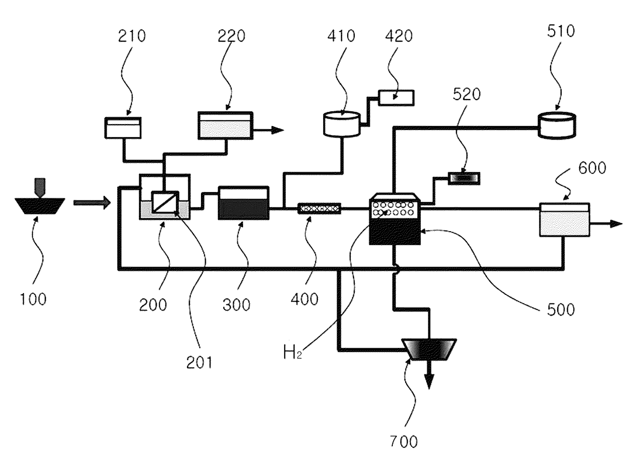
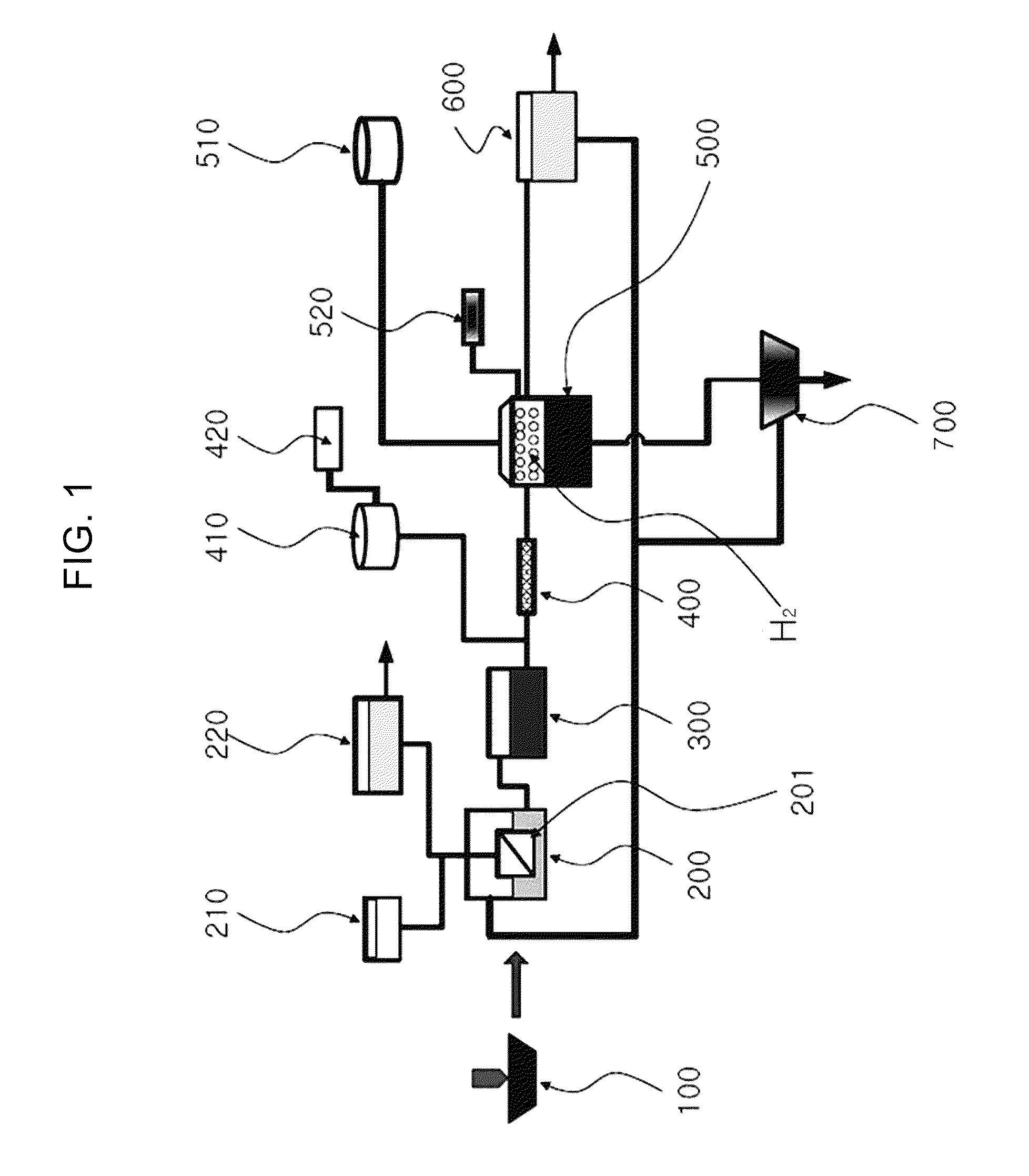
[0041]FIG. 1 is a schematic view illustrating a hydrogen energy production system utilizing silicon wastewater according to the present invention.

[0042]Referring to FIG. 1, the hydrogen energy system utilizing silicon wastewater of the present invention includes an ultrafiltration (“UF”) treatment bath 200, a line mixer 400 and a hydrogen production bath 500.

[0043]The UF treatment bath 200 receives the silicon wastewater, filters the same through a submerged type UF membrane 201 installed inside the UF treatment bath 200, and separates UF treated water and a concentrated silicon waste solution from the wastewater. In this case, the silicon wastewater means a silicon-containing waste solution generated during ingot processing, semiconductor manufacturing, etc...


PUM

PropertyMeasurementUnit
pHaaaaaaaaaa
humidityaaaaaaaaaa
acidityaaaaaaaaaa

Abstract

Disclosed are a hydrogen energy production system utilizing silicon wastewater and a method for production of hydrogen energy using the same. More particularly, the disclosed system includes: a UF treatment bath wherein the silicon wastewater is treated through UF film filtration to separate UF treated water and a concentrated silicon waste solution therefrom; a line mixer connected to the UF treatment bath in order to admix the separated silicon waste solution with an alkaline material fed from the outside; and a hydrogen production bath connected to the line mixer, wherein the concentrated silicon waste solution in the mixture reacts with the alkaline material, in order to produce hydrogen gas. Additionally, a hydrogen energy production method using the foregoing system is also disclosed.

Description

BACKGROUND OF THE INVENTION[0001]1. Field of the Invention[0002]The present invention relates to a system for production of hydrogen energy utilizing silicon wastewater in order to create an additional energy resource, and a method for production of hydrogen energy using the same.[0003]2. Description of the Related Art[0004]As advanced information and communication industries, semiconductor industries, exhaustion of petroleum energy, as well as industries using solar energy to prevent global warming recently come to the fore, demand for silicon wafers is rapidly increasing.[0005]In general, a silicon wafer is fabricated by providing a slurry containing a cutting oil and an abrasive material (i.e., silicon carbide, aluminum oxide, silicon dioxide, etc.) and cutting the wafer using a wire saw.[0006]The cut silicon wafer, which is generally covered with waste slurry admixed with saw dust as well as the used slurry containing the cutting oil and the abrasive material, is then delivered ...

Claims


Application Information

Patent Timeline
Patent Type & Authority Patents(United States)
IPC IPC(8): C01B3/00C01B3/02
CPCY02E60/362C02F2103/346C01B3/065C02F1/444Y02E60/324C01B3/06Y02W10/37Y02E60/36Y02E60/32
Inventor CHOI, CHAE-SEOKHWANG, JI-HYEONKIM, YOUN-KOOK
Owner COWAY ENTECH CO LTD
Why Eureka
Try Eureka