
Hydrophone and pressure balancing device for using for hydrophone

a technology of hydrophone and pressure balancing device, which is applied in the direction of generator/motor, instruments, heat measurement, etc., can solve the problems of deterioration of sensitivity in a low frequency range, limited application range of hydrophone, and high cost of manufacturing commercial hydrophones

Active Publication Date: 2014-02-04
POSTECH ACAD IND FOUND
View PDF10 Cites 0 Cited by
  • Summary
  • Abstract
  • Description
  • Claims
  • Application Information

AI Technical Summary

Benefits of technology

[0011]The present invention has been made in an effort to provide a hydrophone having advantages of capable of using in a high pressure and preventing deterioration of a sensitivity.
[0035]Further, by using a pressure balancing device in which a compressible gas is filled, a hydrophone can be suppressed from being damaged under a high pressure.

Problems solved by technology

Commercial hydrophones are generally manufactured by mechanically coupling many parts including a piezoelectric element such as piezoelectric ceramic or a piezoelectric polymer such as polyvinylidene fluoride (PVDF), and much time and cost are consumed in manufacturing the commercial hydrophones, and an application range thereof may be limited according to a size thereof.
However, when a hydrophone is manufactured in a micro size, a problem that a sensitivity is deteriorated in a low frequency range may occur.
Particularly, when a piezoelectric element is used, generating charges are not enough due to the piezoelectric element in a low frequency band and thus a sensitivity may be deteriorated due to high electrical impedance and electrical noise of an amplifier.
Further, when a sensitive portion of the hydrophone is manufactured in a thin film form, the sensitive portion may be weak to an increasing pressure, i.e., a constant pressure according to the increase of the depth of water.

Method used


Image

  • Hydrophone and pressure balancing device for using for hydrophone
  • Hydrophone and pressure balancing device for using for hydrophone
  • Hydrophone and pressure balancing device for using for hydrophone

Examples


Embodiment Construction

[0048]The present invention will be described more fully hereinafter with reference to the accompanying drawings, in which exemplary embodiments of the invention are shown.

[0049]The drawings and description are to be regarded as illustrative in nature and not restrictive. Like reference numerals designate like elements throughout the specification. Further, in the drawings, a size and thickness of each element are randomly represented for better understanding and ease of description, and the present invention is not limited thereto.

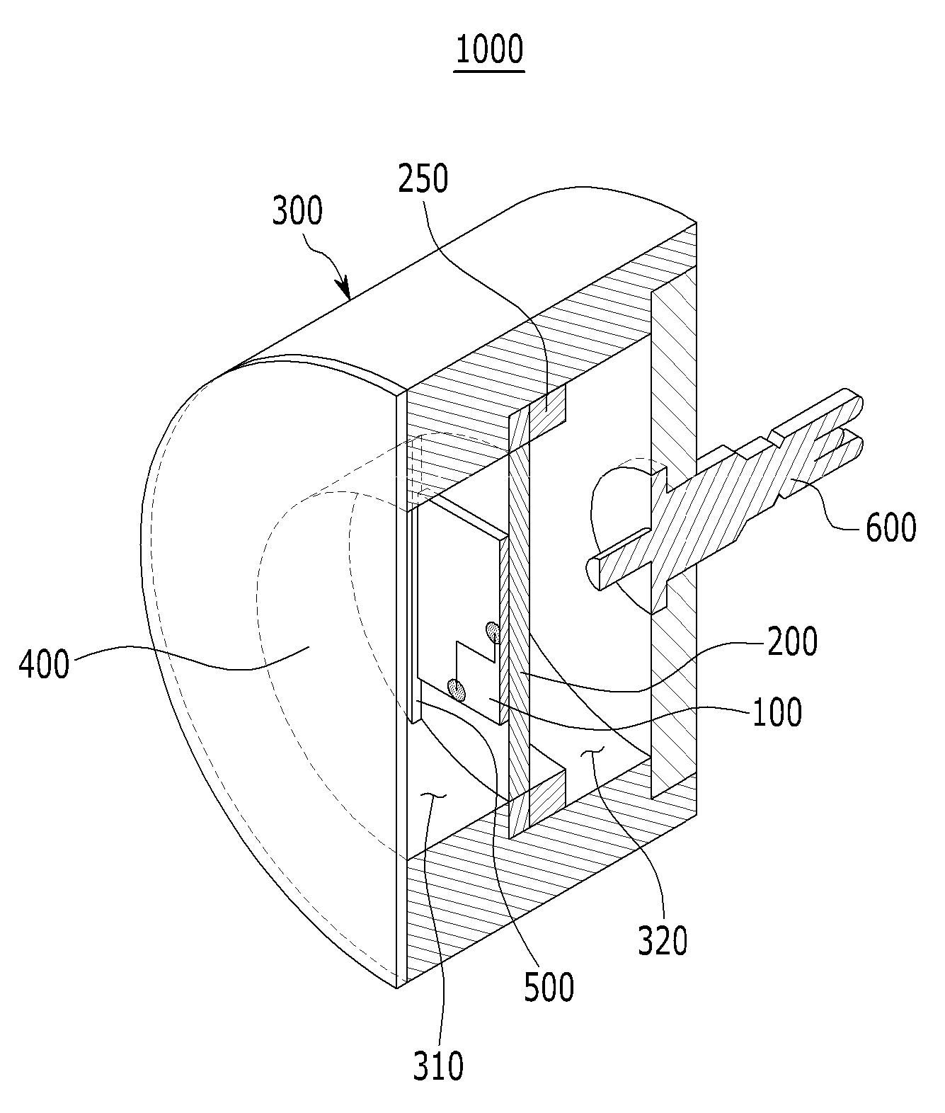
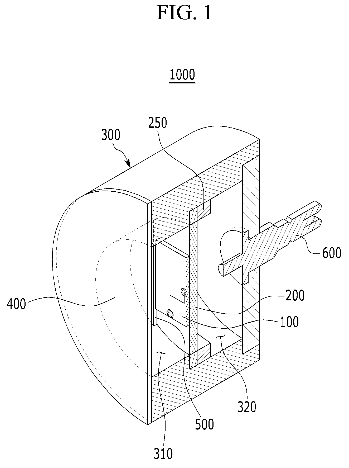
[0050]FIG. 1 is a cross-sectional perspective view of a hydrophone according to a first exemplary embodiment of the present invention and hereinafter, a hydrophone 1000 according to the present exemplary embodiment will be described with reference to FIG. 1.

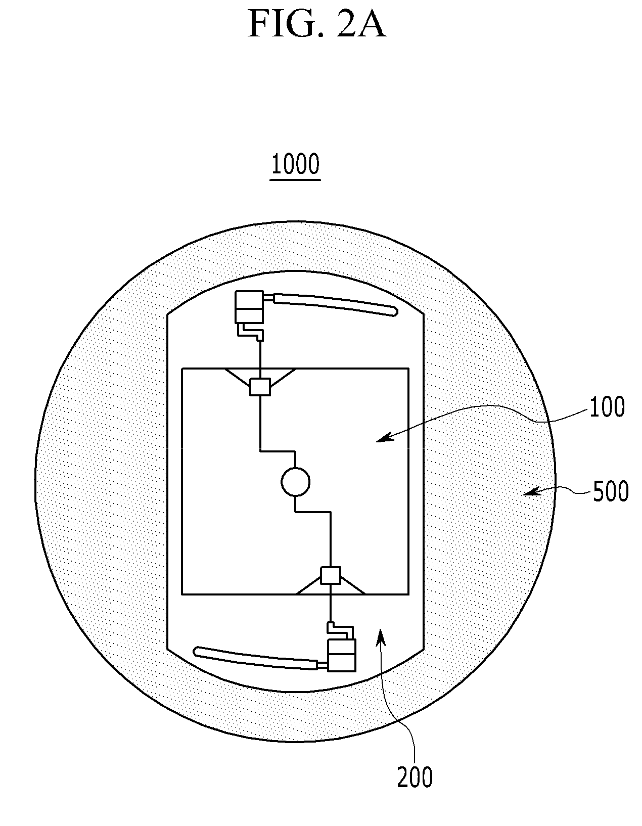
[0051]Referring to FIG. 1, the hydrophone 1000 according to the present exemplary embodiment includes a sensor 100, a PCB 200, a case 300 that houses the sensor 100 and the PCB 200, an elastic membrane...


PUM

PropertyMeasurementUnit
sizeaaaaaaaaaa
thicknessaaaaaaaaaa
thicknessaaaaaaaaaa

Abstract

A sound sensor, a hydrophone including the sound sensor, and a pressure balancing device for using for the hydrophone are provided. The hydrophone includes: a sensor including a sensing part and a pressure balancing part; a printed circuit board (PCB) that is electrically connected to the sensor; a case that houses the sensor and the PCB and that has an opening at one side thereof; an elastic membrane that covers the opening of the case; and a signal line that is electrically connected to the PCB to be extended to the outside of the case. The pressure balancing part includes a diaphragm of a thin film and a support that supports the diaphragm. A pressure balancing hole is formed at one side of the pressure balancing part, and at the inside of the pressure balancing part, a channel that is connected to the pressure balancing hole is formed, and a compressible gas is filled in the channel.

Description

BACKGROUND OF THE INVENTION[0001](a) Field of the Invention[0002]The present invention relates to a hydrophone and a pressure balancing device for using for the hydrophone. More particularly, the present invention relates to a hydrophone including a piezoelectric element and a pressure balancing device for using for the hydrophone.[0003](b) Description of the Related Art[0004]Under water, a water pressure changes according to a depth, and when the depth of water does not change, a water pressure does not change, and this is called a ‘hydrostatic pressure’. However, a sound wave under water changes a pressure by allowing a water particle to generate a vibration of compression waves through a medium of water, and this is called a ‘hydrodynamic pressure’.[0005]A hydrophone is a device that detects sound by detecting a pressure change under water, i.e., a dynamic pressure and converts a voice generating under water to an electrical signal, thereby detecting sound. The hydrophone is desi...

Claims


Application Information

Patent Timeline
Patent Type & Authority Patents(United States)
IPC IPC(8): G01K11/00H04R17/00G01D9/00G01L9/00
CPCH04R1/44G01V1/188G10K11/006G01V1/186H04R17/00
Inventor MOON, WONKYULEE, HAKSUECHOI, SUNGJOON
Owner POSTECH ACAD IND FOUND
Learn More