Temperature monitoring of a light guide in an illumination apparatus

a technology of temperature monitoring and illumination apparatus, which is applied in the direction of printers, projectors, light heating/cooling arrangements, etc., and can solve problems such as second-damag

Active Publication Date: 2014-02-18
NATH GUNTHER
View PDF3 Cites 0 Cited by
  • Summary
  • Abstract
  • Description
  • Claims
  • Application Information

AI Technical Summary

Benefits of technology

[0027]The metallic flexible protection tube of the liquid core light guide is preferably made of stainless steel. The low thermal conductivity of stainless steel effects that the radiation loss of the bubble generates a higher local peak temperature at the protection tube. This higher temperature may be used for a quick contacting between the switching wire and the protection tube. A protection tube of aluminum generates a lower but spatially more extended local temperature rise so that the switching off process takes longer.
[0032]Of course, it is also possible to leave the switching wire in the embodiment uninsulated and cover the outer surface of the protection tube of stainless steel with a thin insulating layer of a low melting polymer instead. This modification works equally well but is more difficult to manufacture when using only one or a plurality of individual switching wires. However, the modification is of particular advantage in the case where a tube-shaped metallic mesh wire, instead of the single or plurality of individual switching wires, is positioned around the protection tube enveloped by the thin walled insulation layer. The mesh wire is simply provided on the complete insulated protection tube so that the wire winding process, which is work-intensive from the manufacturing point of view, can be dispensed with. The polymer insulation layer provides the electrical contact between the mesh wire and the metallic protection tube when reaching the melting point by means of the pressing force of the shrinkage tubing enclosing the metallic mesh wire as described further above. The mesh wire automatically comes to lie in the desired rotation-symmetric manner around the insulated protection tube.
[0033]Also instead of the shrinkage tubing, which exerts the increased pressing force of the insulated switching wire onto the metallic protection tube only in case of a local temperature rise, another coating, e.g. made of an elastomer like silicon, may be chosen which permanently presses the insulated switching wire to the metallic outer tube. The same function could also be achieved by a mesh of metallic wires or plastic fibers which can permanently produce radial pressure with linear tightening. A metallic electrically grounded mesh would moreover involve the advantage of screening from electromagnetic disturbance radiation which may emanate from the long metallic switching wire. Instead of the shrinkage tubing, a heat shrinkage foil may be used which presses the switching wire on the metallic protection tube in case of a temperature rise. Finally, a stretch foil may effect a permanent pressing force of the switching wire.

Problems solved by technology

Because the core of the light guide consists of an aqueous solution having a boiling point which is only slightly above 100° C., even small contaminations of the liquid core or insufficient filtering of the infrared portions of the radiation emitted from the radiation source or a mechanical deforming of the liquid core light guide by exertion of outer forces involve the danger of bubbles being formed in the liquid or a local overheating of the liquid core light guide and a quickly escalating temperature rise of the outer envelope which can damage the liquid core light guide and cause secondary damages.

Method used


Image

  • Temperature monitoring of a light guide in an illumination apparatus
  • Temperature monitoring of a light guide in an illumination apparatus
  • Temperature monitoring of a light guide in an illumination apparatus

Examples


Embodiment Construction

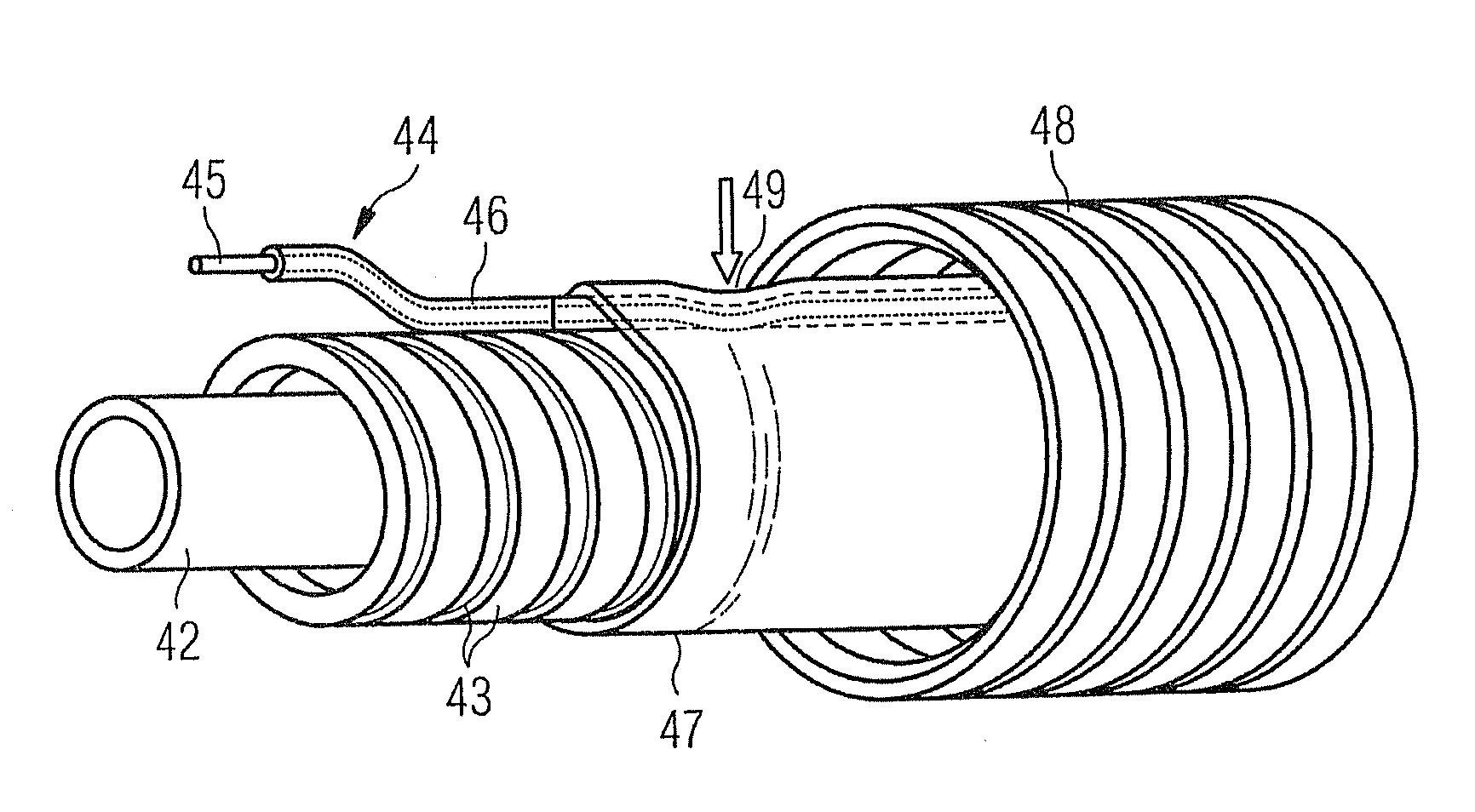
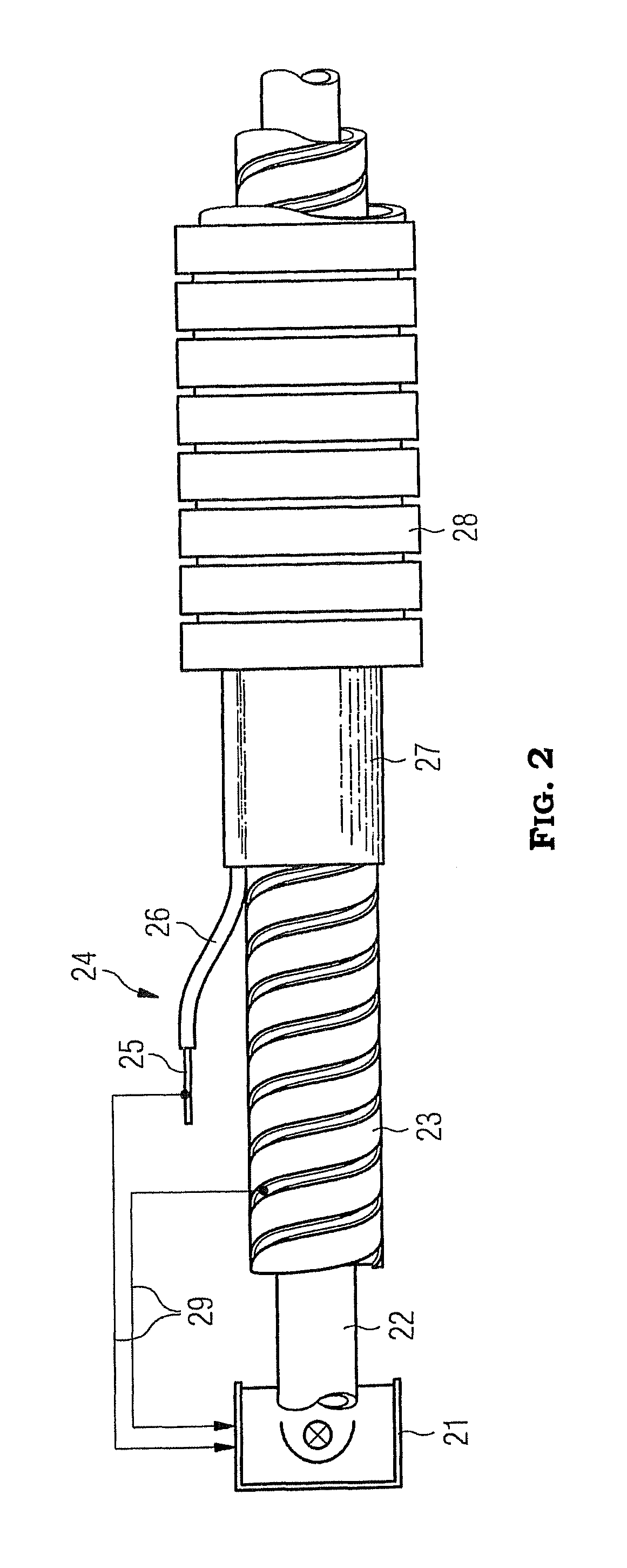
[0025]In the following, a practical embodiment of an illumination apparatus having a video projector lamp of 120 W and a liquid core light guide is given, wherein the light guide has a light active diameter of 5 mm, an emission radiation power of 10 W, a protection tube consisting of a wrapped tube made of stainless steel and an artificially set bubble having a diameter of 3 mm. The illumination apparatus according to this embodiment comprises the temperature monitoring of the present invention which is adapted to trigger switching off of the radiation source due to overheating of the light guide within a few minutes.

[0026]According to the embodiment, a switching wire of 0.5 mm thickness made of annealed stainless steel is used which is insulated by non-cross-linked polyethylene (PE), preferably LDPE (low density PE) or LLDPE (linear low density PE). For the insulation for the switching wire it is also possible to use other polymers having a similarly low melting temperature as PE a...


PUM


Abstract

An illumination apparatus having a radiation source and a light guide coupled thereto. The temperature of the light guide is monitored along its complete length. If a threshold temperature is exceeded, a switching mechanism will be triggered. The switching mechanism switches off the radiation source or triggers a warning signal.

Description

CROSS-REFERENCE TO RELATED APPLICATION[0001]The present application claims the benefit of priority to German Patent Applications No. 10 2010 021 012.9 filed May 21, 2010, No. 10 2010 024 362.0 filed Jun. 18, 2010, and No. 10 2010 026 347.8 filed Jul. 7, 2010, the contents of which are incorporated herein by reference in their entirety.BACKGROUND OF THE INVENTION[0002]The present invention relates to an illumination apparatus having an irradiation source and a light guide coupled thereto. The light guide is flexible and positioned within a metallic protection tube which is flexible as well. The light guide includes a temperature monitoring mechanism which monitors the temperature along the complete length of the metallic flexible protection tube. In case the local threshold temperature is exceeded anywhere on the outer surface of the metallic protection tube, the radiation source is switched off with a delay of only a few minute. A temperature monitoring mechanism of this kind has be...

Claims


Application Information

Patent Timeline
Patent Type & Authority Patents(United States)
IPC IPC(8): G02B6/00
CPCG02B6/032G02B6/4298G03B21/16G02B6/0008G03B21/2093G03B21/20
Inventor NATH, GUNTHER
Owner NATH GUNTHER
Why Eureka
Try Eureka