Modeling for soft error specification

a soft error and specification technology, applied in the field of soft error rate (ser) estimation, can solve the problems of insufficient multi-threading processor approach, inability to model se events in iss or reference architecture, and affecting the processing efficiency of the error encountering thread

Inactive Publication Date: 2014-02-25
GLOBALFOUNDRIES U S INC
View PDF9 Cites 7 Cited by
  • Summary
  • Abstract
  • Description
  • Claims
  • Application Information

AI Technical Summary

Problems solved by technology

However, due to the inherently random nature of SE events and because these events are not always coupled with a specific instruction, the ISS or reference architecture cannot model these SE events.
This presents a challenge in verifying hardware functionality pertaining to detection, and logging such errors, referred to collectively as SE handling.
This approach is inadequate for multi-threading processors because of the presence of multiple concurrent threads, which could be executing completely independent programs.
Here, the proper error handling by the error encountering thread could be hampered by events on other threads.
Furthermore, an error on one thread could leak to another thread causing spurious logging or functional incorrectness.
For example, if a thread sees an error which is then improperly reported to a different thread, the second thread will behave as if the error occurred during execution of its own program, potentially resulting in data corruption.
This enabled early estimation of SE FIT, but had a large margin of error, was labor intensive, and was not regressible in the sense that if the design changed, the work could not easily be modified to account for the changes.
A more accurate estimate was available late in the design phase, using a fault grading (FG) tool, but since it was late in the design phase any defects related to soft error upset (SEU) could not be corrected, or could only be corrected at relatively high cost.
Cost is measured in money, time, or engineering effort, and it is generally recognized that defects found late in a design cycle require more to correct than those found early.

Method used


Image

  • Modeling for soft error specification
  • Modeling for soft error specification
  • Modeling for soft error specification

Examples


Embodiment Construction

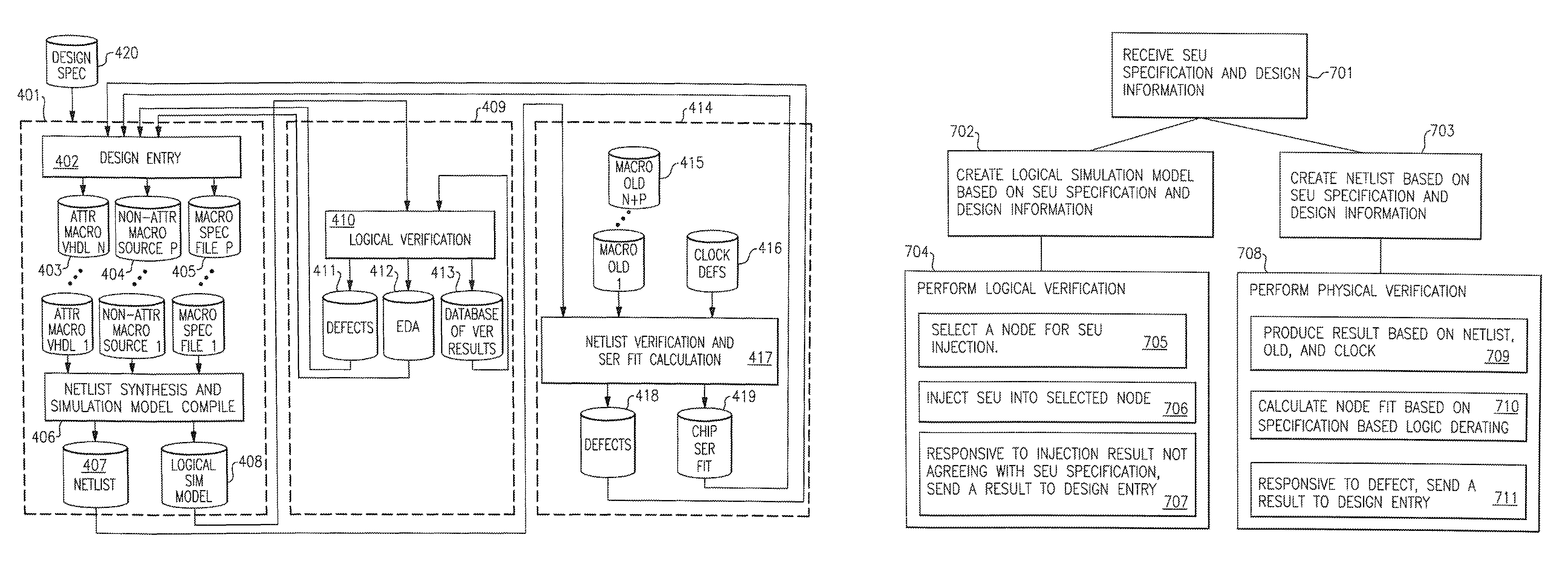
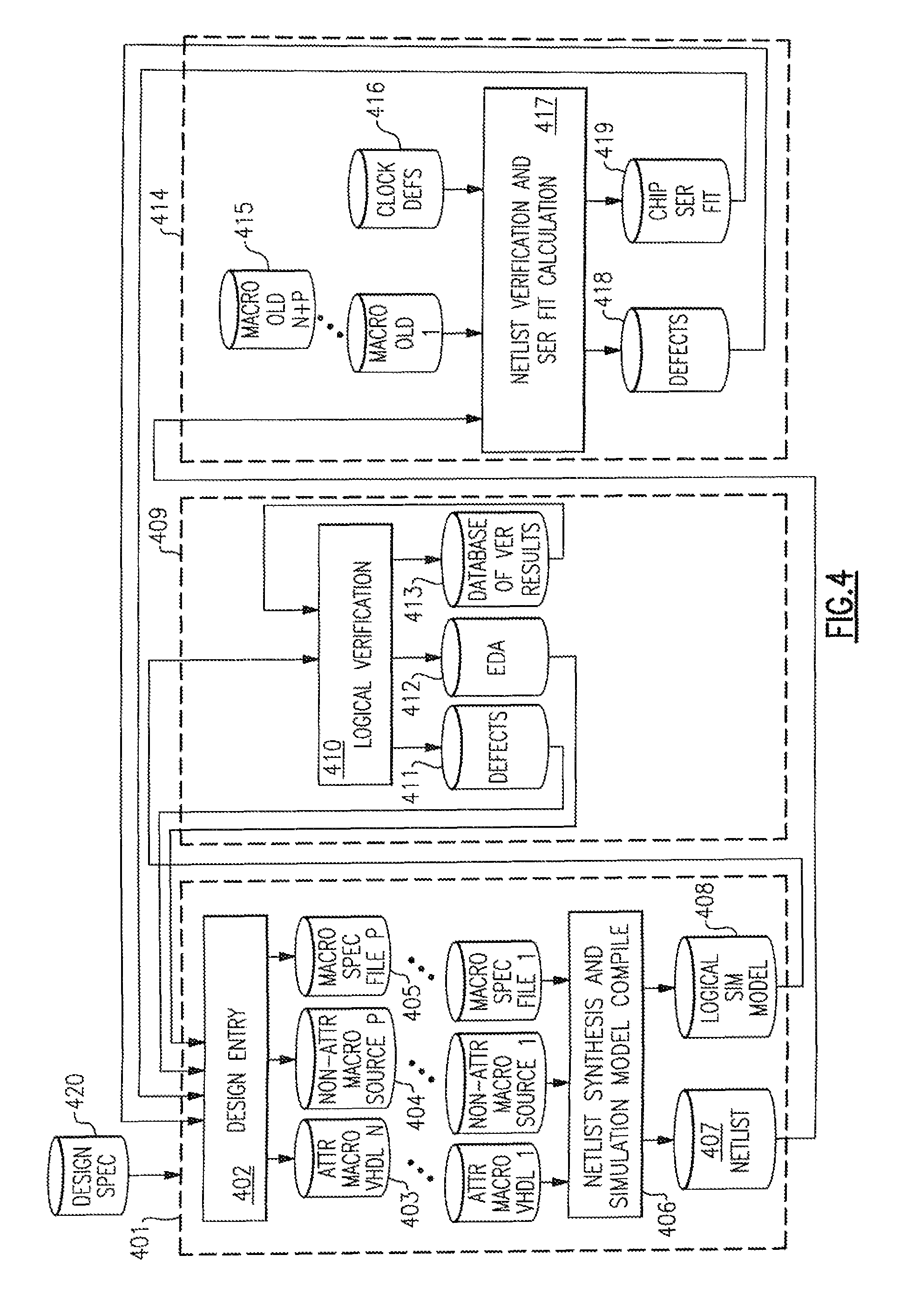
[0024]In accordance with an embodiment of the present invention, an integrated system, methodology, and program product for front end design employing a node-based SEU specification is provided. For description purposes, the embodiment's attributes are stated to be applied to latches in the design, but may also be applied to any node such as a wire, transistor gate, logic element, memory array, register array, latch, etc of the system without any changes to the essence of the invention.

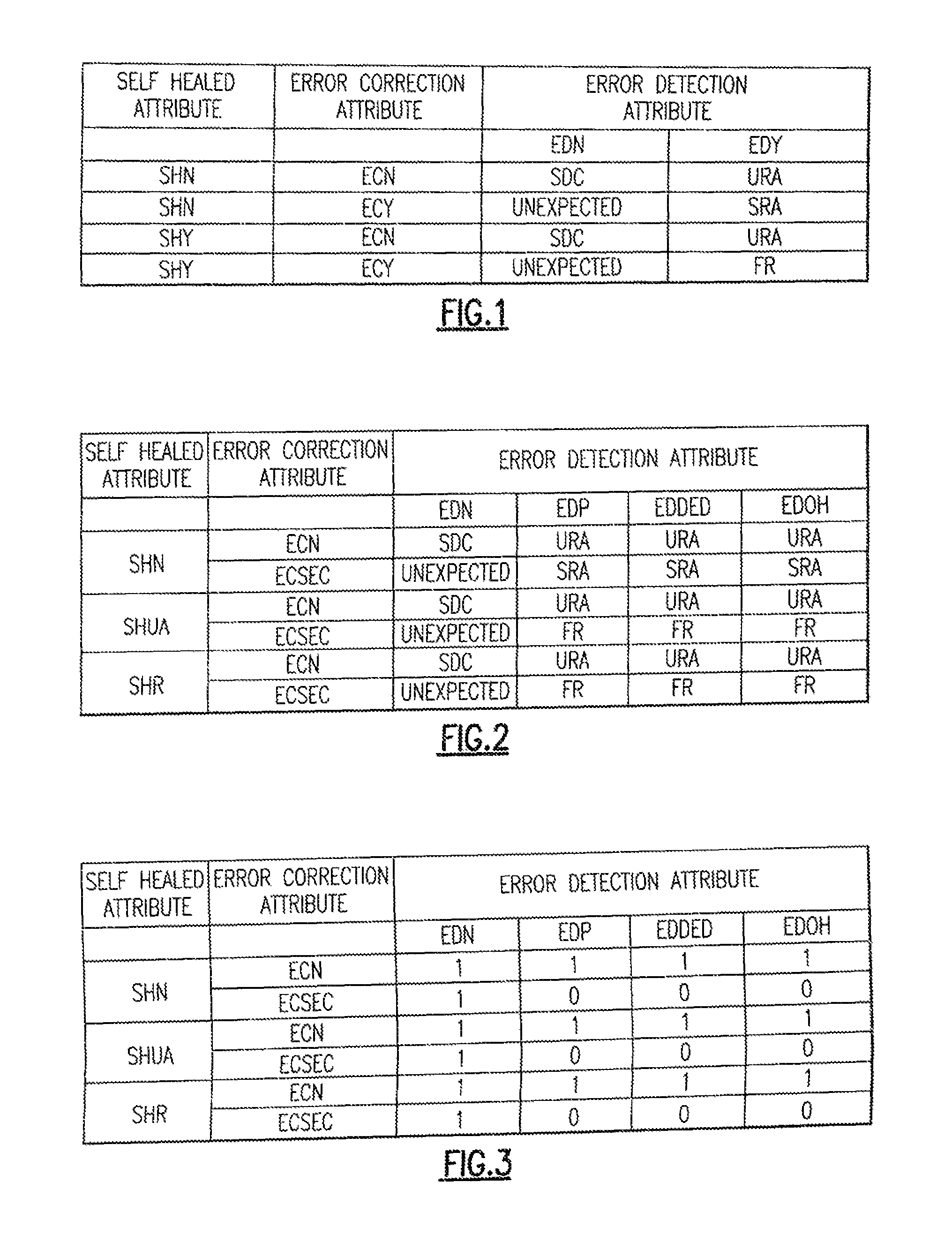
[0025]One embodiment of the present invention introduces a node-based SEU specification, to be attributed uniquely to each latch, which specifies the behavior of the latch relative to an SEU in the categories of error detection, error correction, fault isolation, and self-healing (EDECFISH). This specification enables logical verification of the specification, targeted design changes to improve soft error tolerance, and accurate, regressible calculations of FIT rate due to soft errors. The EDECFISH at...


PUM


Abstract

Soft error modeling of circuits. Soft error upset (SEU) specification and design information is received from a design entry. The SEU specification comprises expected SEU behavior of a node. A logical simulation model is created based on the SEU specification and the design information. A logical verification is performed based on the logical simulation model to produce a first result. The logical verification comprises selecting a first node for injection, injecting an SEU into the first node to produce a first result, and responsive to the first result not agreeing with the SEU specification, providing the first result to the design entry. A netlist based on the SEU specification and the design information is created. The netlist comprises a specification-based-logic-derating derived from the SEU specification. A physical design verification based on the netlist, a logic derating, and clock information is performed. It comprises calculating node failure-in-time based on the specification-based-logic-derating.

Description

BACKGROUND[0001]This invention relates, in general, to soft error rate (SER) estimation, and, in particular, to enabling accurate estimation and validation for integrated circuits (IC or chip) and Application Specific Integrated Circuits (ASIC) or other circuits used in digital system design.[0002]Various subcircuits in integrated circuits and ASICs, such as register files, latches, and memory buffers, store data that is subject to corruption by soft errors (SE). SE occurs, for example, when ionizing radiation causes a latch or node in a memory array to invert its logical value. Most hardware has embedded logic to detect, correct, and log such errors and notify the software of such an event through exceptions. Instruction set simulators (ISS) are often used to verify the proper functioning of the chip in connection with virtual IC modeling the physical implementations of the chip. However, due to the inherently random nature of SE events and because these events are not always coupl...

Claims


Application Information

Patent Timeline
Patent Type & Authority Patents(United States)
IPC IPC(8): G06G7/62G06F11/22G06F17/50
CPCG06F17/5009G06F30/20
Inventor LAMB, KIRK, DAVID
Owner GLOBALFOUNDRIES U S INC
Why Eureka
Try Eureka