Trench isolation structure and method for forming the same

a technology of isolation structure and divot, which is applied in the direction of basic electric elements, electrical apparatus, and semiconductor devices, can solve the problems of leakage and device performance degradation, and more device performance degradation, so as to reduce the impact of the divot on the performance of the semiconductor device, and reduce the size of the divot

Active Publication Date: 2014-04-01
INST OF MICROELECTRONICS CHINESE ACAD OF SCI
View PDF10 Cites 0 Cited by
  • Summary
  • Abstract
  • Description
  • Claims
  • Application Information

AI Technical Summary

Benefits of technology

[0005]The problem to be solved by the present invention is to provide a trench isolation structure and a method of forming the same to reduce the impact of the divot on device performance.
[0038]Compared with the prior art, the present invention has the following advantages.
[0039]For the trench isolation structure according to the present technical solution, the trenches are filled with a crystalline dielectric layer, so that the interface between the dielectric layer and the semiconductor substrate is tighter, which may reduce the size of the divot, thus reduce the impact of the divot on semiconductor device performances.
[0040]Furthermore, according to the present technical solution, the upper surface of the dielectric layer filled in the trenches may be higher than the surface of the semiconductor substrate, which may further reduce the size of the divot and improve semiconductor device performances.
[0041]Furthermore, according to the present technical solution, impurity ions may be introduced into the crystalline dielectric layer in the trenches so that the lattice constant of the dielectric layer may be tuned to have larger or smaller than the lattice constant of the semiconductor substrate, so as to produce compressive stress or tensile stress within the dielectrics and thus improve the performances of a PMOS transistor or an NMOS transistor.

Problems solved by technology

The divot may cause problems such as leakage and device performance degradation.
Moreover, as the sizes of devices shrink, the divot's relative size compared with the device formed between the STI becomes larger, resulting in even more device performance degradation.

Method used


Image

  • Trench isolation structure and method for forming the same
  • Trench isolation structure and method for forming the same
  • Trench isolation structure and method for forming the same

Examples


first embodiment

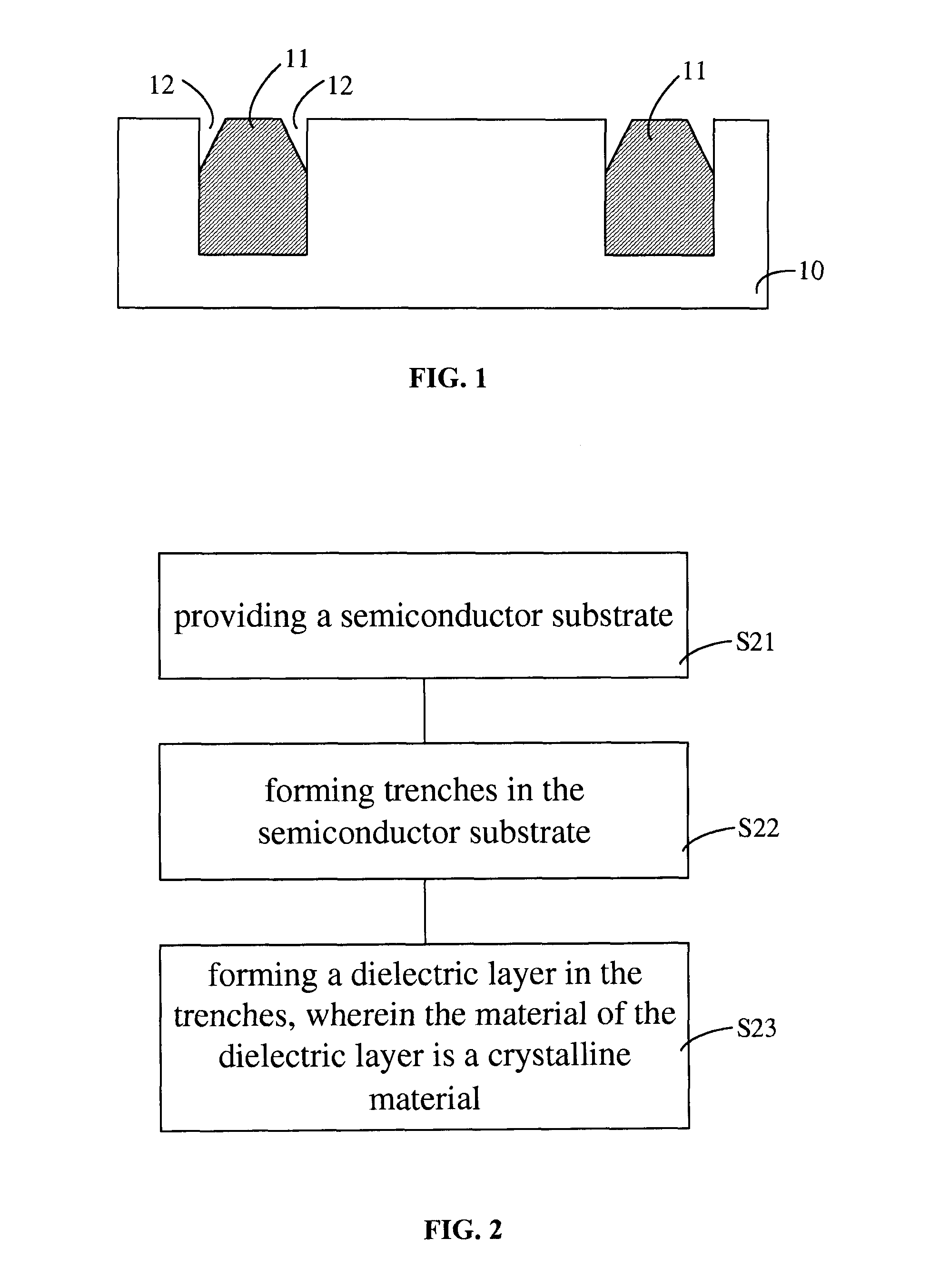
[0054]FIG. 2 is a flow chart of a method for forming a trench isolation structure according to the present invention. As shown in FIG. 2, the method includes:

[0055]step S21: providing a semiconductor substrate;

[0056]step S22: forming trenches on the semiconductor substrate; and

[0057]step S23: forming a dielectric layer in the trenches, wherein the material of the dielectric layer is a crystalline material.

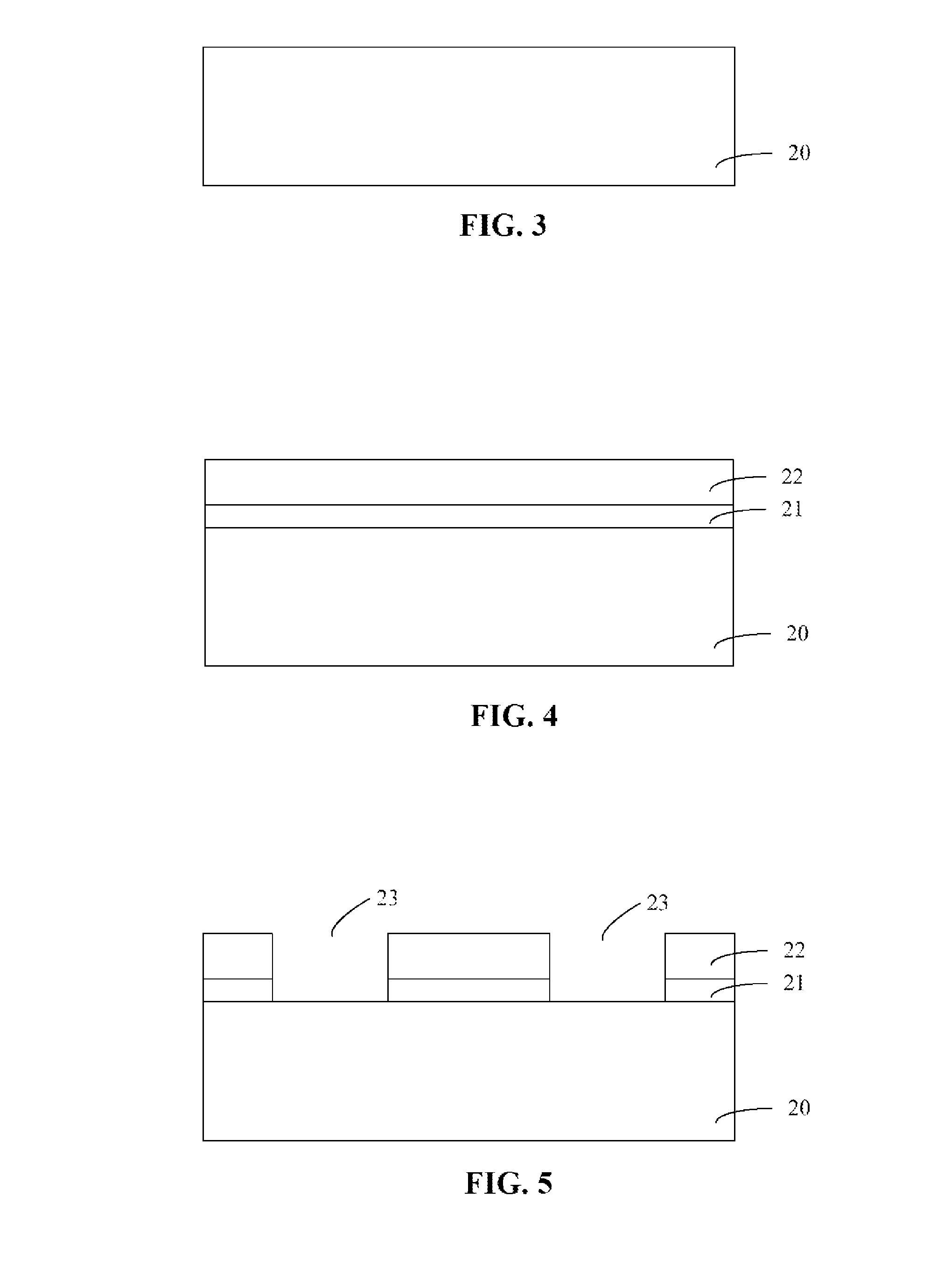
[0058]FIGS. 3-8 illustrate a method for forming a trench isolation structure according to a first embodiment of the present invention with sectional views of intermediate structures. The embodiment is described below with reference to FIGS. 2 and 3-8.

[0059]With reference to FIGS. 2 and 3, step S21 is performed: providing a semiconductor substrate. In particular, a semiconductor substrate 20 is provided, and the semiconductor substrate 20 may be a silicon substrate, a silicon-germanium substrate, a III-V compound substrate (e.g., gallium arsenide, indium phosphide, or gallium nitrid...

second embodiment

[0070]FIG. 10 shows a cross-sectional view of a trench isolation structure formed according to the present invention. The trench isolation structure includes: a semiconductor substrate 30, and trenches formed on the semiconductor substrate 30 and filled with a dielectric layer 31, wherein the material of the dielectric layer 31 is a crystalline material. In particular, the dielectric layer 31 has a multi-layer structure including a first dielectric layer 31a and a second dielectric layer 31b. Of course, in other embodiments, the dielectric layer 31 may include more dielectric layers, e.g., three layers or four layers. Impurity ions may be introduced into the dielectric layer 31 such that the lattice constant of the dielectric layer 31 is larger or smaller than the lattice constant of the semiconductor substrate 30. A MOS transistor may be formed on the semiconductor substrate 30 between the trenches. The MOS transistor may include a gate stack 32, and a source and a drain in the sem...

third embodiment

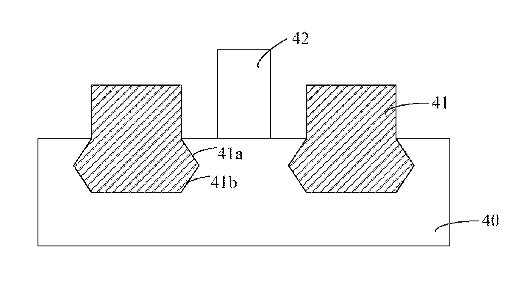
[0071]FIG. 11 shows a cross-sectional view of a trench isolation structure formed according to the present invention. The trench isolation structure includes: a semiconductor substrate 40, and trenches formed on the semiconductor substrate 40 and filled with a dielectric layer 41, wherein the material of the dielectric layer 41 is a crystalline material. In particular, the sidewalls of the trench form a diamond shape and include an upper sidewall 41a and a lower sidewall 41b connected with each other. The upper sidewall 41a and the lower sidewall 41b are in the {111} lattice plane of the semiconductor substrate 40. Impurity ions may be introduced into the dielectric layer 41 such that the lattice constant of the dielectric layer 41 is larger or smaller than the lattice constant of the semiconductor substrate 40. A MOS transistor may be formed on the semiconductor substrate 40 between the trenches. The MOS transistor may include a gate stack 42, and a source and a drain in the semico...


PUM


Abstract

A trench isolation structure and a method of forming the same are provided. The trench isolation structure includes: a semiconductor substrate, and trenches formed in the semiconductor substrate and filled with a dielectric layer, where the material of the dielectric layer is a crystalline material. By using the present invention, the size of the divot can be reduced, and device performances can be improved.

Description

CROSS-REFERENCE TO RELATED APPLICATION[0001]This application is a Section 371 national stage application of, and claims priority to, International Application No. PCT / CN2011 / 073180 filed on Apr. 22, 2011, which claims priority to Chinese Application No. 201010557395.7 filed on Nov. 23, 2010. Both the International Application and the Chinese Application are incorporated herein by reference in their entireties.FIELD OF THE INVENTION[0002]The present invention relates to the field of semiconductor fabrication, and in particular, to a trench isolation structure and a method for forming the same.BACKGROUND OF THE INVENTION[0003]In the deep-submicron era of semiconductor technology, shallow trench isolation (STI) is widely used for the isolation between active areas of semiconductor devices such as metal-oxide-semiconductor (MOS) transistors. Generally, the STI process includes: forming a shallow trench in the semiconductor substrate by, e.g., etching, for the isolation between the activ...

Claims


Application Information

Patent Timeline
Patent Type & Authority Patents(United States)
IPC IPC(8): H01L21/76H01L29/00
CPCH01L29/02H01L21/76232H01L21/76224
Inventor ZHONG, HUICAIZHAO, CHAOLIANG, QINGQING
Owner INST OF MICROELECTRONICS CHINESE ACAD OF SCI
Why Eureka
Try Eureka