
Compositions of neutral layer for directed self assembly block copolymers and processes thereof

a technology of self-assembly block and neutral layer, which is applied in the field of compositions of neutral layer for directed self-assembly block copolymers and processes thereof, can solve the problems of difficult to achieve further reduction of pattern dimensions, the limited dimension of integrated circuit features, and the region exposed to radiation to become less removable with a developer solution or by conventional ic plasma processing

Active Publication Date: 2014-04-08
MERCK PATENT GMBH
View PDF8 Cites 50 Cited by
  • Summary
  • Abstract
  • Description
  • Claims
  • Application Information

AI Technical Summary

Benefits of technology

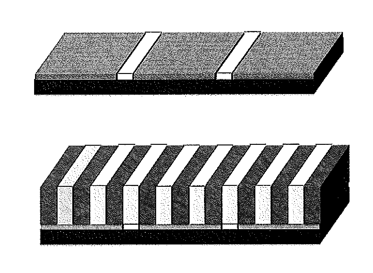
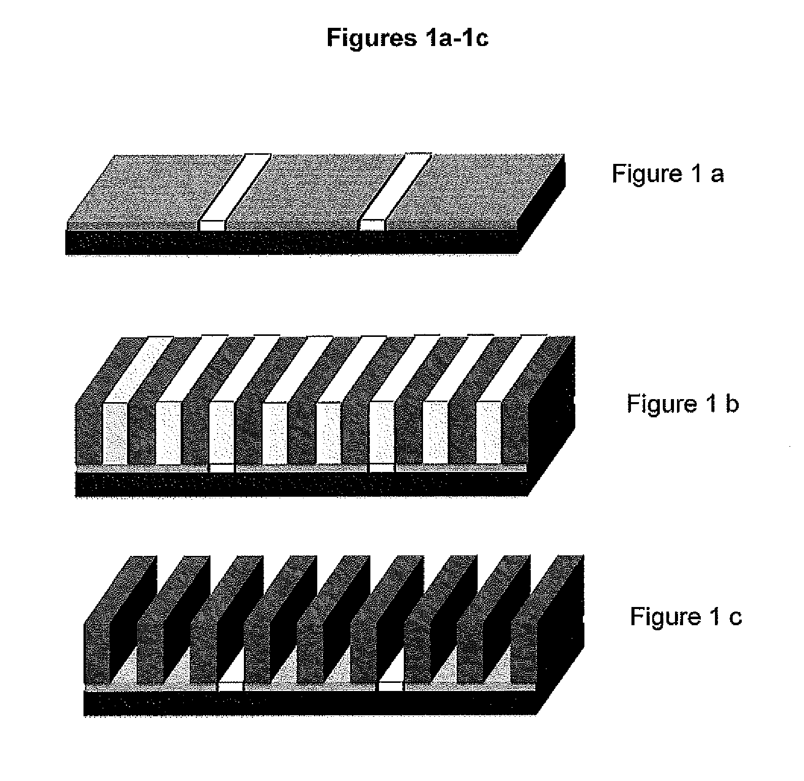
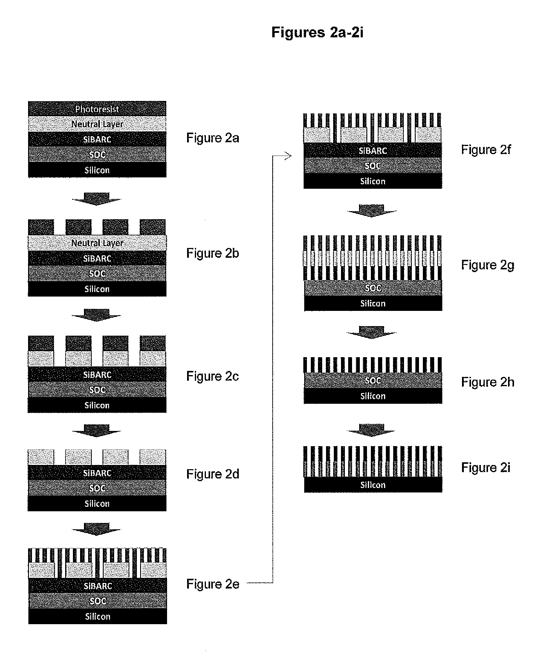
[0003]In the graphoepitaxy directed self assembly method, the block copolymers self organizes around a substrate that is pre-patterned with conventional lithography (Ultraviolet, Deep UV, e-beam, Extreme UV (EUV) exposure source) to form repeating topographical features such as a line / space (L / S) or contact hole (CH) pattern. In an example of a L / S directed self assembly array, the block copolymer can form self-aligned lamellar regions which can form parallel line-space patterns of different pitches in the trenches between pre-patterned lines, thus enhancing pattern resolution by subdividing the space in the trench between the topographical lines into finer patterns. For example, a diblock copolymer which is capable of microphase separation and comprises a block rich in carbon (such as styrene or containing some other element like Si, Ge, Ti) which is resistant to plasma etch, and a block which is highly plasma etchable or removable, can provide a high resolution pattern definition. Examples of highly etchable blocks can comprise monomers which are rich in oxygen and which do not contain refractory elements, and are capable of forming blocks which are highly etchable, such as methylmethacrylate. The plasma etch gases used in the etching process of defining the self assembly pattern typically are those used in processes employed to make intergrated circuits (IC). In this manner very fine patterns can be created in typical IC substrates than were definable by conventional lithographic techniques, thus achieving pattern multiplication. Similarly, features such as contact holes can be made denser by using graphoepitaxy in which a suitable block copolymer arranges itself by directed self assembly around an array of contact holes or posts defined by conventional lithography, thus forming a denser array of regions of etchable and etch resistant domains which when etched give rise to a denser array of contact holes. Consequently, graphoepitaxy has the potential to offer both pattern rectification and pattern multiplication.
[0004]In chemical epitaxy or pinning chemical epitaxy the self assembly of the block copolymer is formed around a surface that has regions of differing chemical affinity but no or very slight topography to guide the self assembly process. For example, the surface of a substrate could be patterned with conventional lithography (UV, Deep UV, e-beam EUV) to create surfaces of different chemical affinity in a line and space (L / S) pattern in which exposed areas whose surface chemistry had been modified by irradiation alternate with areas which are unexposed and show no chemical change. These areas present no topographical difference, but do present a surface chemical difference or pinning to direct self assembly of block copolymer segments. Specifically, the directed self assembly of a block copolymer whose block segments contain etch resistant (such as styrene repeat unit) and rapidly etching repeat units (such as methyl methacrylate repeat units) would allow precise placement of etch resistant block segments and highly etchable block segments over the pattern. This technique allows for the precise placement of these block copolymers and the subsequent pattern transfer of the pattern into a substrate after plasma or wet etch processing. Chemical epitaxy has the advantage that it can be fined tuned by changes in the chemical differences to help improve line-edge roughness and CD control, thus allowing for pattern rectification. Other types of patterns such as repeating contact holes (CH) arrays could also be pattern rectified using chemoepitaxy.
[0006]Thus, there is a need for neutral layer compositions which when formed into a layer remain neutral to the self assembly block copolymer and yet are not damaged by processing steps of directed self assembly techniques, and can further enhance the lithographic performance of the directed self assembly materials and processes, especially reducing the number of processing steps and providing better pattern resolution with good lithographic performance. The present invention relates to novel processes and novel neutral layer compositions which form layers which are neutral to the self assembly block copolymer and provide patterns with good lithographic performance.

Problems solved by technology

Conversely, in negative photoresists, UV radiation transmitted through a mask causes the regions exposed to radiation to become less removable with a developer solution or by conventional IC plasma processing.
When using conventional lithographic exposure processes, the dimensions of features of the integrated circuit feature are limited.
Further reduction in pattern dimensions are difficult to achieve with radiation exposure due to limitations related to aberrations, focus, proximity effects, minimum achievable exposure wavelengths and maximum achievable numerical apertures.
The need for large-scale integration has led to a continued shrinking of the circuit dimensions and features in the devices.
In the past, the final resolution of the features has been dependent upon the wavelength of light used to expose the photoresist, which has its own limitations.

Method used


Image

  • Compositions of neutral layer for directed self assembly block copolymers and processes thereof
  • Compositions of neutral layer for directed self assembly block copolymers and processes thereof
  • Compositions of neutral layer for directed self assembly block copolymers and processes thereof

Examples


example 1

Synthesis of Neutral Polymer 1

[0050]A solution was prepared containing 0.1642 g of AIBN, 2.6129 g of 4-vinylbenzocyclobutene (0.0200 mole), 2.0944 g of styrene (0.0201 mole) and 6.001 g of methyl methacrylate (0.0599 mole) in a 250 ml flask with a magnetic bar and cold water condenser. To this solution was then added 25.44 g of 2-butanone giving a clear solution after stirring. After nitrogen gas was passed to purge for 30 minutes, the flask was immersed in 80° C. oil bath. Polymerization was carried out at this temperature for 19 hours. The reaction solution was then allowed to cool to room temperature and poured slowly into methanol with stirring to precipitate the crude polymer. The crude polymer obtained was isolated by filtering. The polymer was purified by dissolving it into 2-butanone and precipitated again in methanol. The purified polymer was dried in a 50° C. vacuum oven until constant weight (6.8 g). The polymer had a Mw of 18515 g / mol and Mn of 11002 g / mol. This polymer ...

example 2

Synthesis of Neutral Polymer 2

[0051]A solution was prepared containing 0.165 g of AIBN, 2.6188 g of 4-vinylbenzocyclobutene (0.0201 mole), 6.2705 g of styrene (0.0602 mole) and 2.0022 g of methyl methacrylate (0.0200 mole) in a 250 ml flask with a magnetic bar and cold water condenser. To this solution was then added 25 g of 2-butanone giving a clear solution after stirring. After nitrogen gas was passed to purge for 30 minutes, the flask was immersed in a 80° C. oil bath. Polymerization was carried out at this temperature for 22 hrs. The reaction solution was then allowed to cool to room temperature and poured slowly into methanol under stirring to precipitate the crude polymer. The crude polymer obtained was isolated by filtering. The polymer was purified by dissolving it into 2-butanone and precipitated it again in methanol. The purified polymer was dried in a 50° C. vacuum oven until constant weight (5.8 g). The polymer had an Mw of 16,180 g / mol and Mn of 9,342 g / mol. This polym...

example 3

Synthesis of Neutral Polymer 3

[0052]A solution was prepared containing 0.33 g of AIBN, 7.81 g of 4-vinylbenzocyclobutene (0.0600 mole), 10.45 g of styrene (0.100 mole) and 4.0 g of methyl methacrylate (0.0399 mole) in a 300 ml flask with a magnetic bar and cold water condenser. To this was added 52.6 g of 2-butanone giving a clear solution after stirring. After nitrogen gas was passed to purge for 30 minutes, the flask was immersed in an 80° C. oil bath. Polymerization was carried out at this temperature for 20 hours. The reaction solution was allowed to cool to room temperature and poured slowly into methanol under stirring to precipitate the crude polymer. The crude polymer obtained was isolated by filtering. The polymer was then purified by dissolving it into 2-butanone and precipitated into methanol again. The purified polymer was dried in a 50° C. vacuum oven until constant weight (11.6 g). The polymer had a Mw of 17086 g / mol and Mn of 10005 g / mol. This polymer was designated i...


PUM

PropertyMeasurementUnit
temperaturesaaaaaaaaaa
thicknessaaaaaaaaaa
thicknessaaaaaaaaaa

Abstract

The present invention relates to novel neutral layer compositions and methods for using the compositions. The neutral layer composition comprises at least one random copolymer having at least one unit of structure (1), at least one unit of structure (2) and at least one unit of structure (3)where R1 is selected from the group consisting of a C1-C8 alkyl, C1-C8 fluoroalkyl moiety, C1-C8 partially fluorinated alkyl, C4-C8 cycloalkyl, C4-C8 cyclofluoroalkyl, C4-C8 partially fluorinated cycloalkyl, and a C2-C8 hydroxyalkyl; R2, R3 and R5 are independently selected from a group consisting of H, C1-C4 alkyl, CF3 and F; R4 is selected from the group consisting of H, C1-C8 alkyl, C1-C8 partially fluorinated alkyl and C1-C8 fluoroalkyl, n ranges from 1 to 5, R6 is selected from the group consisting of H, F, C1-C8 alkyl and a C1-C8 fluoroalkyl and m ranges from 1 to 3.

Description

FIELD OF THE INVENTION[0001]The invention relates to novel neutral layer compositions and novel methods for using the neutral layer compositions for aligning microdomains of directed self-assembling block copolymers (BCP). The compositions and processes are useful for fabrication of electronic devices.DESCRIPTION OF THE INVENTION[0002]Directed self assembly of block copolymers is a method useful for generating smaller and smaller patterned features for the manufacture of microelectronic devices in which the critical dimensions (CD) of features on the order of nanoscale can be achieved. Directed self assembly methods are desirable for extending the resolution capabilities of microlithographic technology. In a conventional lithography approach, ultraviolet (UV) radiation may be used to expose through a mask onto a photoresist layer coated on a substrate or layered substrate. Positive or negative photoresists are useful and these can also contain a refractory element such as silicon to...

Claims


Application Information

Patent Timeline
Patent Type & Authority Patents(United States)
IPC IPC(8): C08F118/02C08L33/12G03F7/20
CPCC08F293/00C08L53/00G03F7/20G03F7/2037G03F7/00B82Y10/00G03F7/0002B82Y40/00C08F212/08C08F212/32C09D125/14C09D125/16C08F220/14
Inventor WU, HENGPENGCAO, YIHONG, SUNGEUNYIN, JIANPAUNESCU, MARGARETANEISSER, MARK O.LIN, GUANYANG
Owner MERCK PATENT GMBH
Learn More