Method and apparatus for cooling a planar workpiece in an evacuated environment with dynamically moveable heat sinks

Inactive Publication Date: 2014-04-22
SEAGATE TECH LLC
View PDF5 Cites 6 Cited by
  • Summary
  • Abstract
  • Description
  • Claims
  • Application Information

AI Technical Summary

Benefits of technology

The invention provides a cooling system for workpieces that improves the cooling rate by controllably driving the heat sinks towards and away from each other to adjust the spacing between the workpiece and the heat sinks. This allows for the insertion and removal of the workpiece without the need for a large margin between the surfaces of the heat sinks, while still maintaining a relatively high production throughput.

Problems solved by technology

However, normal heat conduction processes work very poorly in the vacuum environment.
Further, cooling of substrates or disks by exposure to the atmosphere while still hot severely limit the usefulness of such substrates or disks for particular applications.
Additionally, uncontrolled cooling and / or cooling in atmosphere can adversely affect coating quality by virtue of the diffusion of different coatings at elevated temperature.
The main disadvantage of such a system is that the act of touching such a relatively thin substrate may do harm to one or more surfaces that have to be maintained in pristine condition.
Further, the low mass and the need to handle the substrates only at their edges make them difficult to conductively couple with a heat sink.
Furthermore, newer products have thicker substrates and require higher cooling rates before an overcoat process.

Method used


Image

  • Method and apparatus for cooling a planar workpiece in an evacuated environment with dynamically moveable heat sinks
  • Method and apparatus for cooling a planar workpiece in an evacuated environment with dynamically moveable heat sinks
  • Method and apparatus for cooling a planar workpiece in an evacuated environment with dynamically moveable heat sinks

Examples


Embodiment Construction

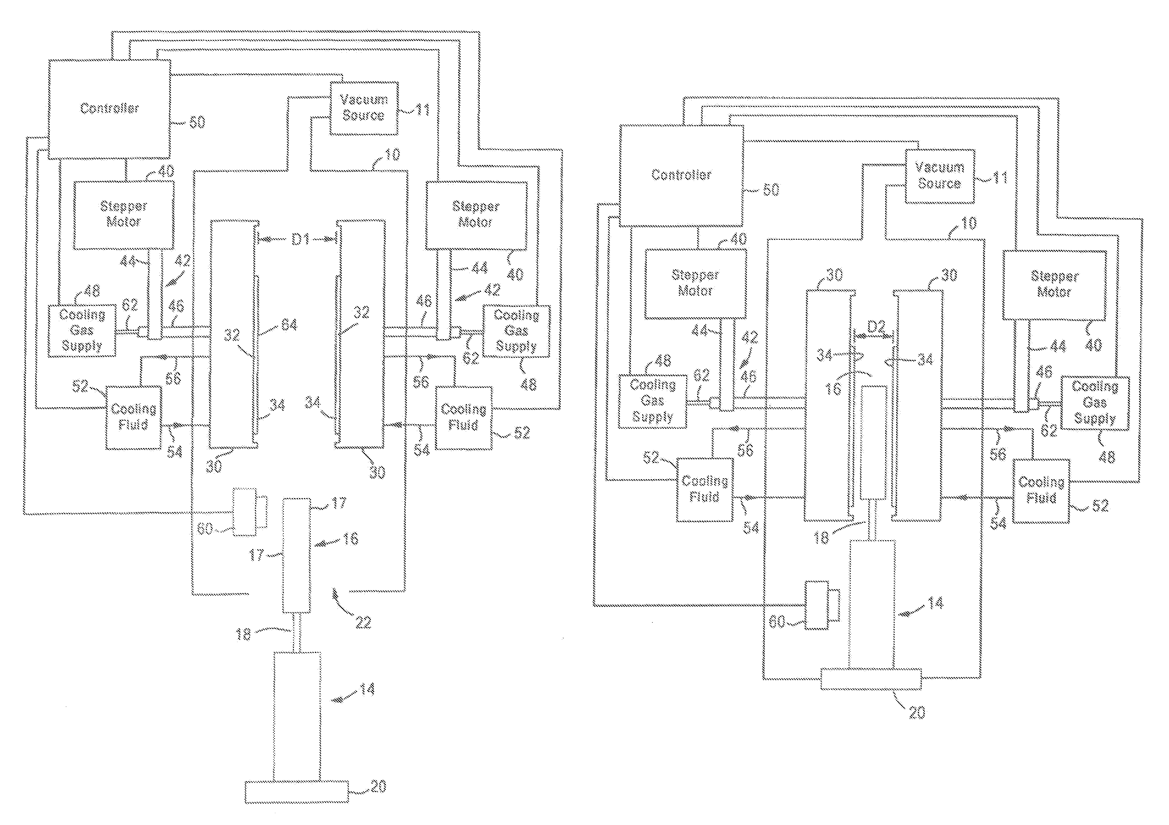
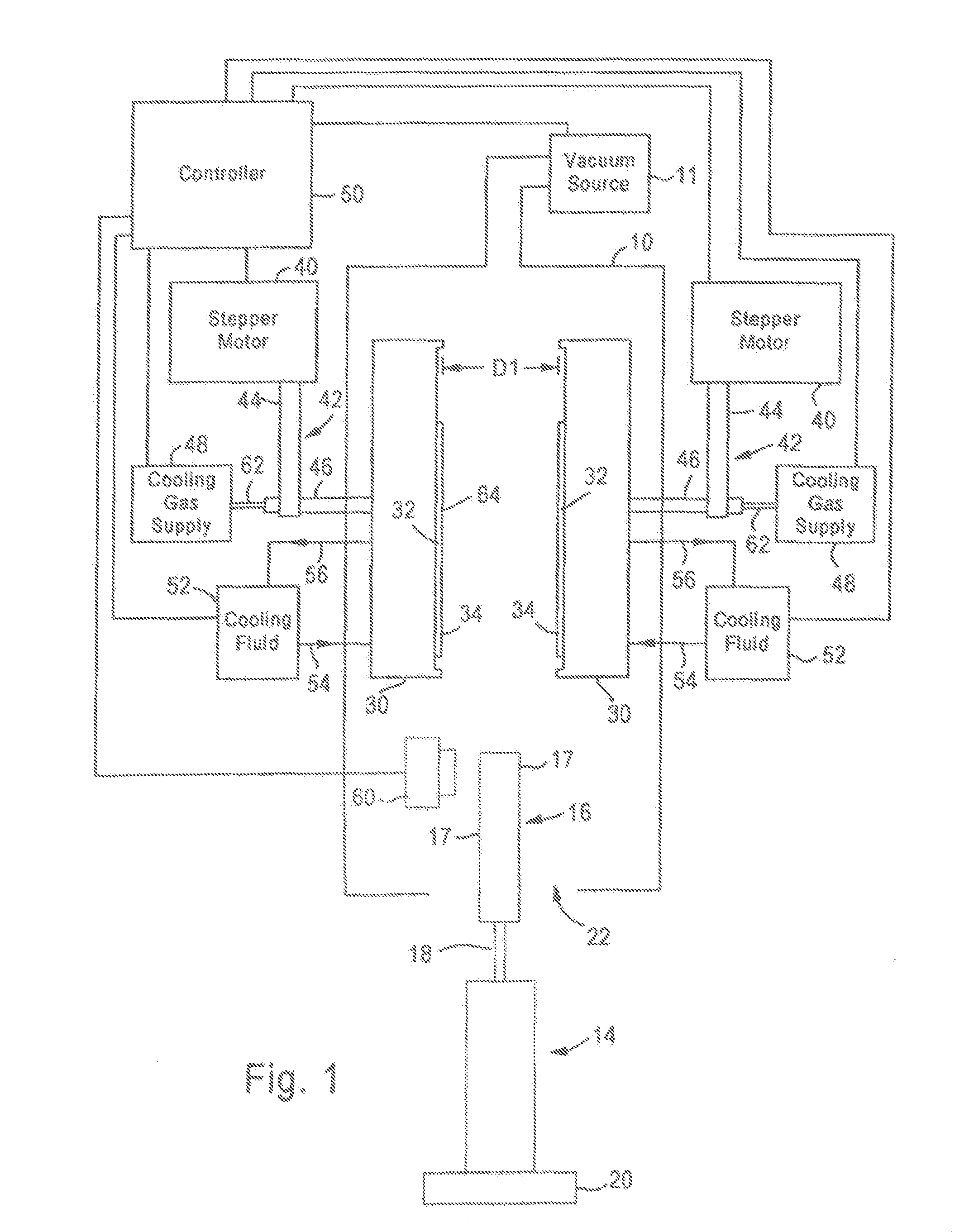
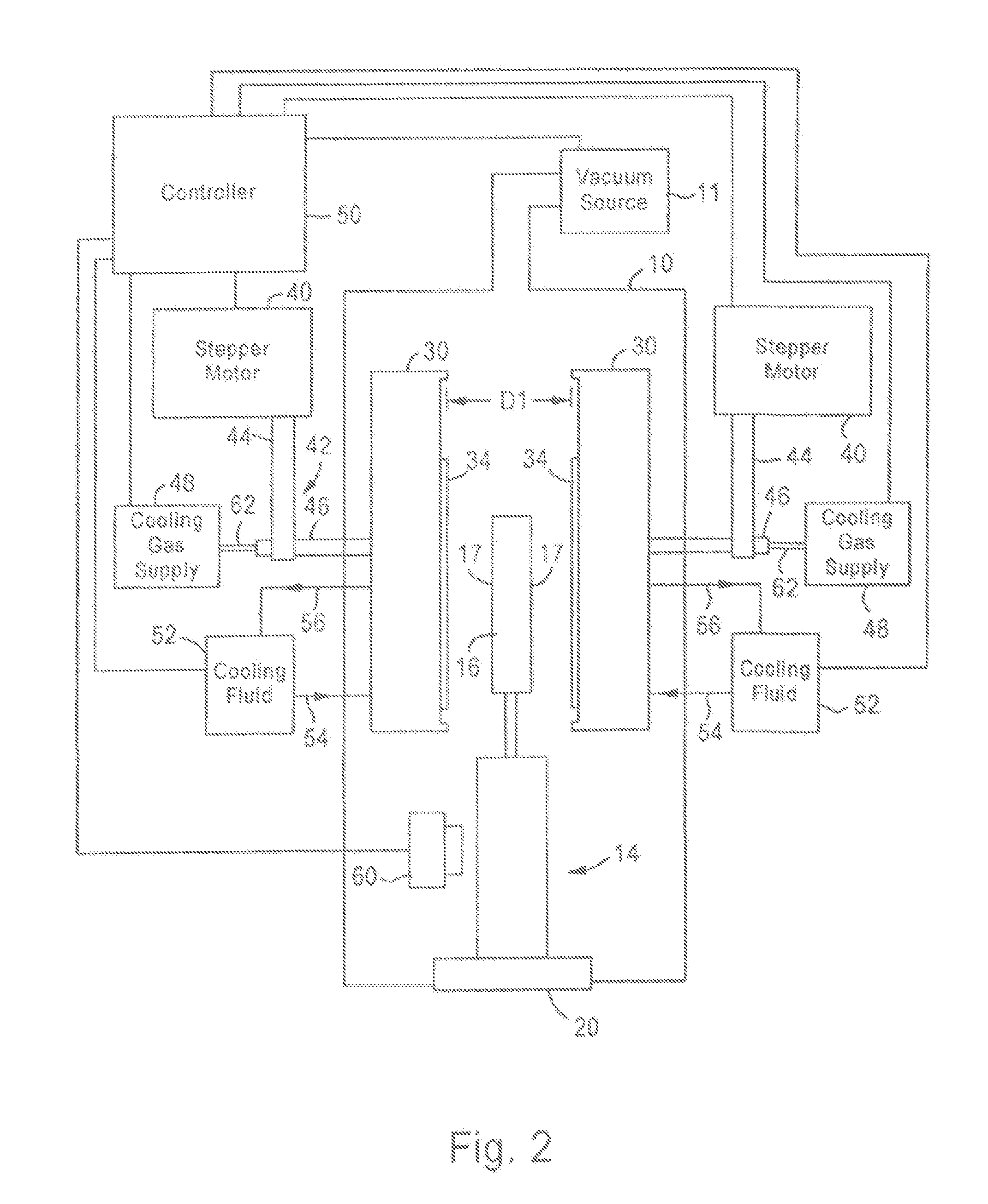
[0026]The present invention addresses and solves problems related to the cooling of workpieces and articles, such as substrates for recording disks, in an evacuated environment. In particular, the present invention solves problems, at least in part, related to the need for increased cooling rate to either improve throughput by increasing the cooling rate, or maintaining the throughput for substrates having greater thicknesses. This is achieved, in part, by methods and apparatus for cooling a workpiece in an evacuated environment in which a drive arrangement is provided to controllably drive the parallel surfaces of the heat sinks towards and away from each other. This allows for the heat sinks to be spaced a greater distance apart to permit insertion of the workpiece between the heat sinks, without damage to the heat sinks, followed by driving the heat sinks closer to the surfaces of the workpiece for the cooling process itself. By careful positioning, the gap between the surfaces o...


PUM

PropertyMeasurementUnit
Distanceaaaaaaaaaa
Distanceaaaaaaaaaa
Circumferenceaaaaaaaaaa

Abstract

An apparatus and method for cooling a planar workpiece, such as a substrate of a recording disk, in an evacuated environment has a heat exchanging structure with at least two heat sinks having substantially parallel facing surfaces disposed within a vacuum chamber. A drive arrangement is connected to the heat sinks to controllably and dynamically drive the parallel facing surfaces of the heat sinks towards and away from each other.

Description

RELATED APPLICATIONS[0001]This application claims priority to Provisional Application 60 / 477,858, filed on Jun. 11, 2003, the entire contents of which are hereby incorporated by reference.FIELD OF THE INVENTION[0002]The present invention relates to the manufacture of planar workpieces or other articles, including recording disks, and more particularly, to systems and methods for cooling the workpieces during the manufacturing process.BACKGROUND OF THE INVENTION[0003]Thin substrates, such as those used for magnetic disks, normally require high vacuum processing. This processing generally involves heating of the substrate to a desired temperature and applying different coatings by sputtering or similar physical vapor deposition processes. The high vacuum processes facilitate very high polarity coating depositions and the achievement of a variety of properties that are controlled by such parameters as background pressure, coating rate, and substrate temperature.[0004]Control of substra...

Claims


Application Information

Patent Timeline
IPC IPC(8): F28F13/08H01L21/00F28F13/00F28F23/00
CPCH01L21/67109
Inventor YI, CHANG BOKTANAKA, TATSURUMCLEAOD, PAUL
Owner SEAGATE TECH LLC
Why Eureka
Try Eureka