However, the addition of the second
inlet flow to the impeller leads to a complication in the construction of the flow-routing part of the pump due to the mutual intersection of the exhaust (pressurized) flow with one of the two intake flows to the dual intake impeller.
One part of the outlet flow continues to move between inlets, while the other part keeps rotating in the circular outlet, thereby reducing the pump efficiency.
The increased speed of the dual inlet impeller pump shaft and the reduction of the effective intake flow area due to interference between inlet and outlet flows result in greater relative speed of
inlet flow at the point of impeller entry and thus to a greater drop in pressure at the impeller inlet, which lowers anti-
cavitation properties and service life of the pump.
In order to maintain continuous,
cavitation-free pump operation it is necessary to increase the relative
gas pressure in the reactor's
gas chamber, but it is limited and shouldn't exceed 0.05 MPa due to the constraints of its casing strength based on practical limits for reactor size, quantity of
metal used, and sealing assemblies design.
Furthermore,
casting elements are used due to the complexity of constructing flowing parts of the dual inlet impeller, lowering the quality of pump manufacturing technologies, which leads to increased wall thickness in the flowing part,
mass and size dimensions and higher pump manufacturing costs.
The large hydraulic resistance at the inlet flows due to the flow bending from the axial direction to a radial one, as well as the limited inlet flow section decrease the pump efficiency, anti-
cavitation properties and service life.
Besides the use of elements with
geometric similarity in pump construction, this fails to achieve dynamic similarity on the operating rim of the impeller and therefore fails to balance the
workload of the impeller rims.
The following are the main disadvantages of this
pump design:
Inconsistency in
geometric similarity of input to the upper and lower impeller rim, a much greater hydraulic resistance, and greater non-uniformity of the velocity field attributable to the upper rim significantly reduce its anti-cavitation properties and as a consequence, its service life.
Minimizing the pressure loss at the exit from the guide vanes, the pump achieves great pressure losses in the form of leaks along the air gaps, upper and lower, in the pump casing, as the gaps come under the
pump pressure from the annular collector, which reduces the efficiency of the pump.
The main disadvantages of the pump are the same as in the aforementioned design:
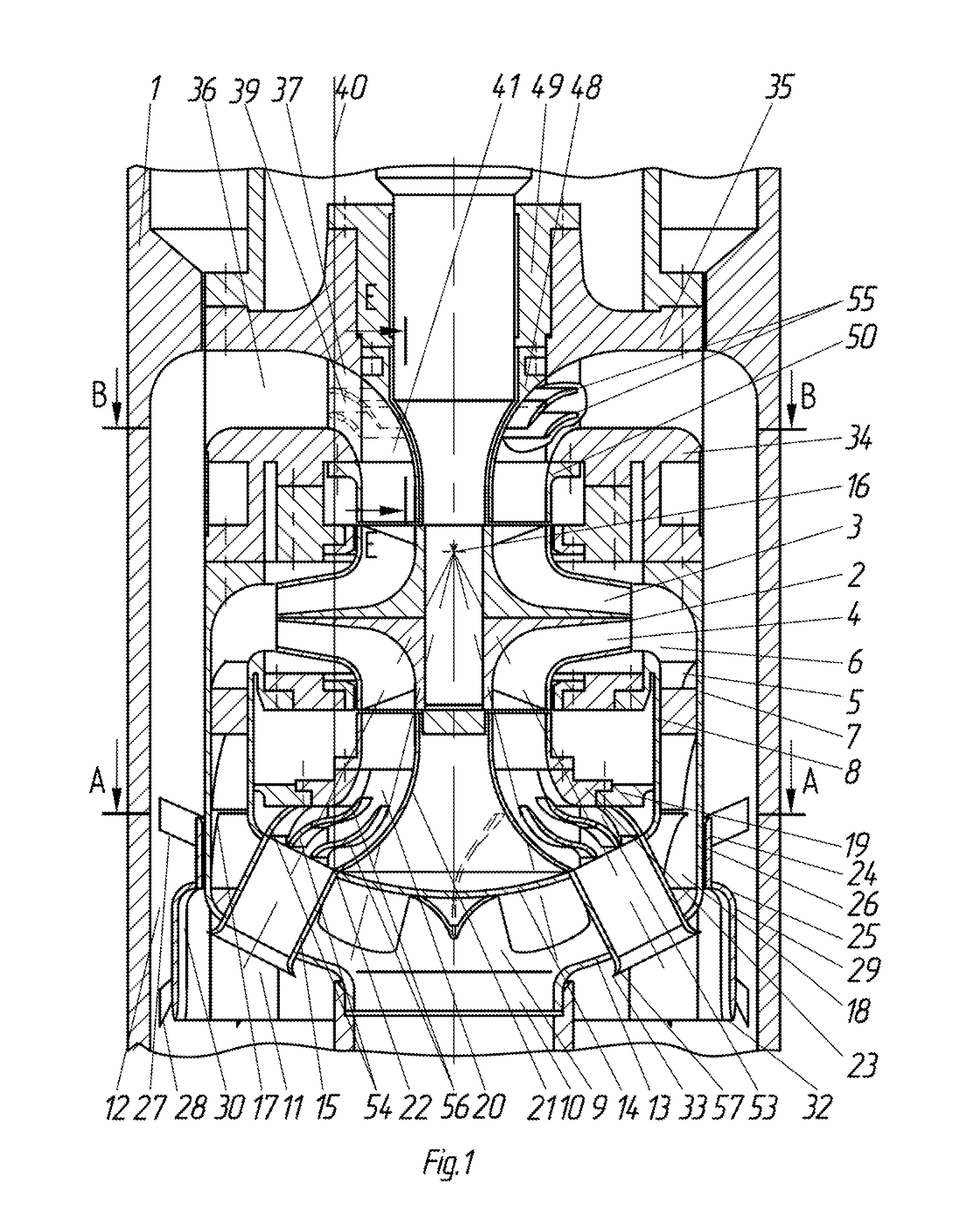
The intersection of the outlet and inlet flows in the cross section of the pump does not provide a minimum pump
diameter.
Great hydraulic resistance and greater non-uniformity of the velocity field attributable to the upper rim, and additionally the negative effect of the rotating shaft on the velocity field upon entry to the upper rim significantly reduce its anti-cavitation properties and as a consequence, its service life.
The low efficiency of the pump is due to the large hydraulic resistance at the flow exit from the blade outlet into the overflow channels, positioned at a right angle, where vortices form and fill the outlet section.
The disadvantages of the described
pump design are as follows:
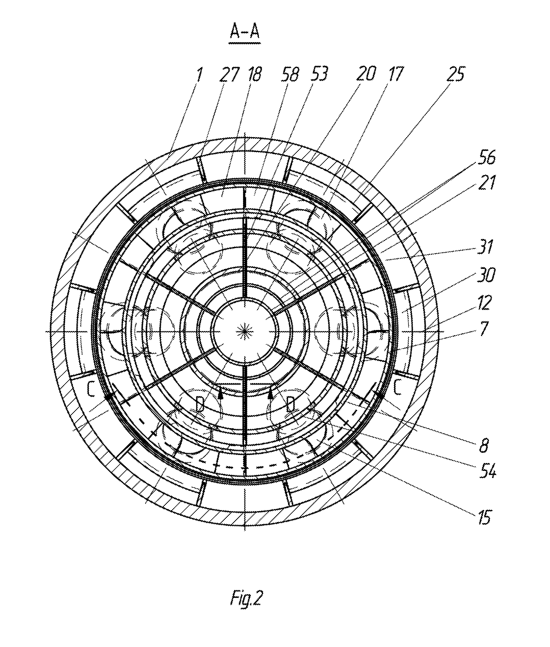
As a result of the intersection in the center plane of the annular outlet's inlet channels with the lower rim it is impossible to achieve a minimized outer pump diameter.
Additionally, the location of the annular guide vane in the center impeller plane between the annular outlet and impeller is not effective and increases the outer diameter of the pump by the width of the annular guide vane.
Complexity of the pump's flow parts design.
In view of the complex
geometric form of the
inlet channel profile in the pump,
casting elements are used, which lower the
production quality of the pump's flow parts due to the sinks that form in them that are subsequently refined in the manufacturing process.
The use of
casting increases thickness of the flow parts walls, size and
mass dimensions and the cost of manufacturing the pump.
Low pump efficiency.
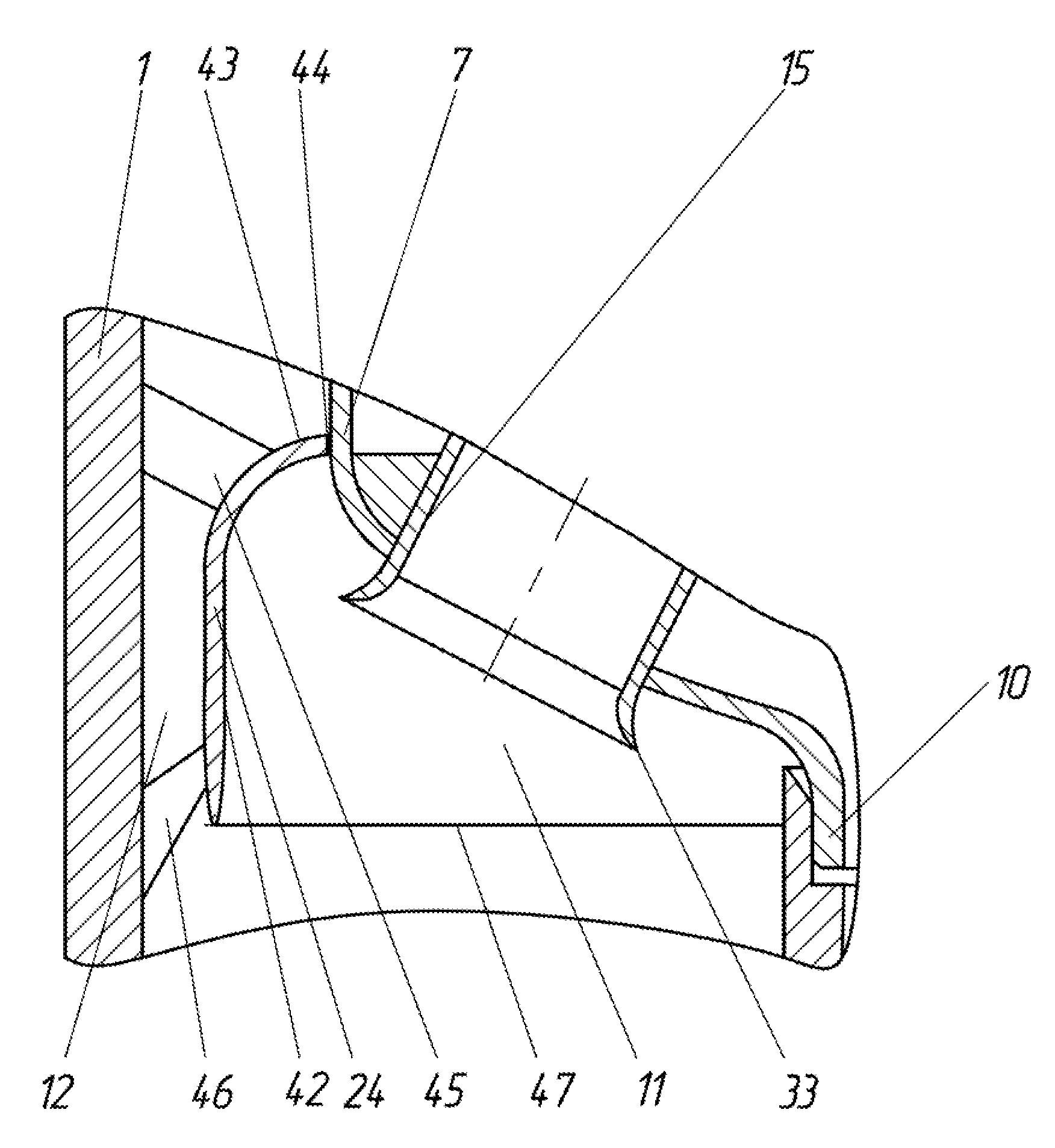
An imperfection in diverting the flow after the annular guide vane along the passage between the inlet channels reduces the efficiency of the pump.
After the guiding vane, the rotating annular pressure flow has a high
peripheral speed and when crossing the center plane with inlet channels at 90° suffers significant hydraulic resistance from the
impact against the sidewall of the
inlet channel in the form of vortex formation, which crowd the section along the vertical passage down between inlet channels and significantly lower pump efficiency.
In addition, lower pump efficiency also contributes to significant hydraulic resistance from the inlet to the upper rim due to
crowding of the channel-shaped section that replicates the lower rim.
During pump construction, the use of inlets in the form of separate radial current flows at the impeller entrance does not provide a good velocity field around the entire entrance section upon suction, which reduces its efficiency, anti-cavitation properties and service life.
Lower anti-cavitation properties and service life of the pump.
The increased rotational speed of the pump shaft to the dual inlet impeller and the
crowding of the section where flow is supplied to the impeller are due to the
mutual influence of inlet and outlet channels on each other lead to an increase in the
relative velocity of the flow at the inlet to the impeller and consequently to an even greater reduction in pressure on the impeller inlet, which reduces the anti-cavitation properties and service life of the pump.
To maintain continuous and cavitation-free operation it is necessary to increase the excess
gas pressure in the reactor cavity, which leads to
increased stress on the
solid housing of the reactor and reduces its service life.
Problems with flow inlets to the impeller.
In pump construction, when implementing
geometric similarity in the inlet flow to the upper and lower impeller rims, the upper impeller rim is in the worst operating conditions due to the negative effect of the rotating shaft surface on the incoming radial-axial flow.
The rotating shaft curls the incoming flow to the upper impeller rim and introduces additional irregularity to the velocity field with the formation of vortices on the inlet rim, which increases the
relative velocity of the flow upon impeller suction and reduces its anti-cavitation properties.
Furthermore, the upper impeller rim is in the worst operating conditions in relation to the lower rim because the smaller hydrostatic lift of the amount of geometrical differences between markers of the upper and lower rims.
Rim operation is far from balanced and demands further improvement to
pump design.
However, exclusion of the influence of axial flows on one another through the sides is not achieved, which leads to vortex formation, which extend deep into the pump impeller and distort the velocity field at the impeller inlet.
