N-channel and P-channel end-to-end finFET cell architecture with relaxed gate pitch

a cell architecture and gate pitch technology, applied in cad circuit design, computer aided design, instruments, etc., can solve the problems of gate conductors that can be susceptible to warping or other distortion, gate conductors that traverse the inter-block insulator can be compromised, and the requirements of low power and compact layout are becoming more demanding. , to achieve the effect of reducing the length of the channel, reducing the risk of off-state leakage, and increasing the gate-to-sour

Active Publication Date: 2014-05-13
SYNOPSYS INC
View PDF9 Cites 25 Cited by
  • Summary
  • Abstract
  • Description
  • Claims
  • Application Information

AI Technical Summary

Benefits of technology

[0008]An integrated circuit is described that includes a substrate, with first and second sets of semiconductor fins arranged on a grid pattern having first and second axes. The semiconductor fins in the first set can be aligned parallel with the first axis of the grid. The semiconductor fins in the second set of semiconductor fins can be aligned parallel with the first axis of the grid. A patterned gate conductor layer can include a plurality of gate elements on corresponding fins in the first and second sets of semiconductor fins, the gate elements being disposed over channel regions that separate first and second ends of the corresponding semiconductor fins. At least one patterned conductor layer overlying the patterned gate conductor layer, and a plurality of interlayer connectors connecting conductors in the at least one patterned conductor layer to gate elements in the patterned gate conductor and to the first and second ends of the semiconductor fins in the first and second sets of fins can be used to interconnect elements of a functional cell. In an implementation with a relaxed gate pitch, wherein the interlayer connectors have first and second axis contact pitches; the semiconductor fins in the first set can have a first axis finFET block pitch that is at least three times the first axis contact pitch, a second axis fin pitch that is at least one times the second axis contact pitch. Therefore, the finFET configuration is laid out to enable interlayer connections at the source, the gate, and the drain along the fin of a particular finFET. A relaxed gate pitch in this configuration enables implementations of finFET block architectures with finFETs having, for example, increased channel lengths (to suppress random variations and suppress off-state leakage), increased the gate-to-source / drain spacer widths (to reduce parasitic gate-to-drain capacitance), increased source / drain sizes (to reduce the S / D contact resistance), or combinations of some of the above.

Problems solved by technology

FinFETs have gained acceptance recently as the requirements of low power and compact layout have become more demanding.
For finFET blocks, the channels of the transistors comprise narrow fins that can be susceptible to warping or other distortion when formed in regions of unbalanced stress, such as can occur at the edges adjacent to the inter-block insulators.
Also, for smaller feature sizes, the reliability of gate conductors traversing the inter-block insulators can be compromised by the non-uniformity of the structures.

Method used


Image

  • N-channel and P-channel end-to-end finFET cell architecture with relaxed gate pitch
  • N-channel and P-channel end-to-end finFET cell architecture with relaxed gate pitch
  • N-channel and P-channel end-to-end finFET cell architecture with relaxed gate pitch

Examples


Embodiment Construction

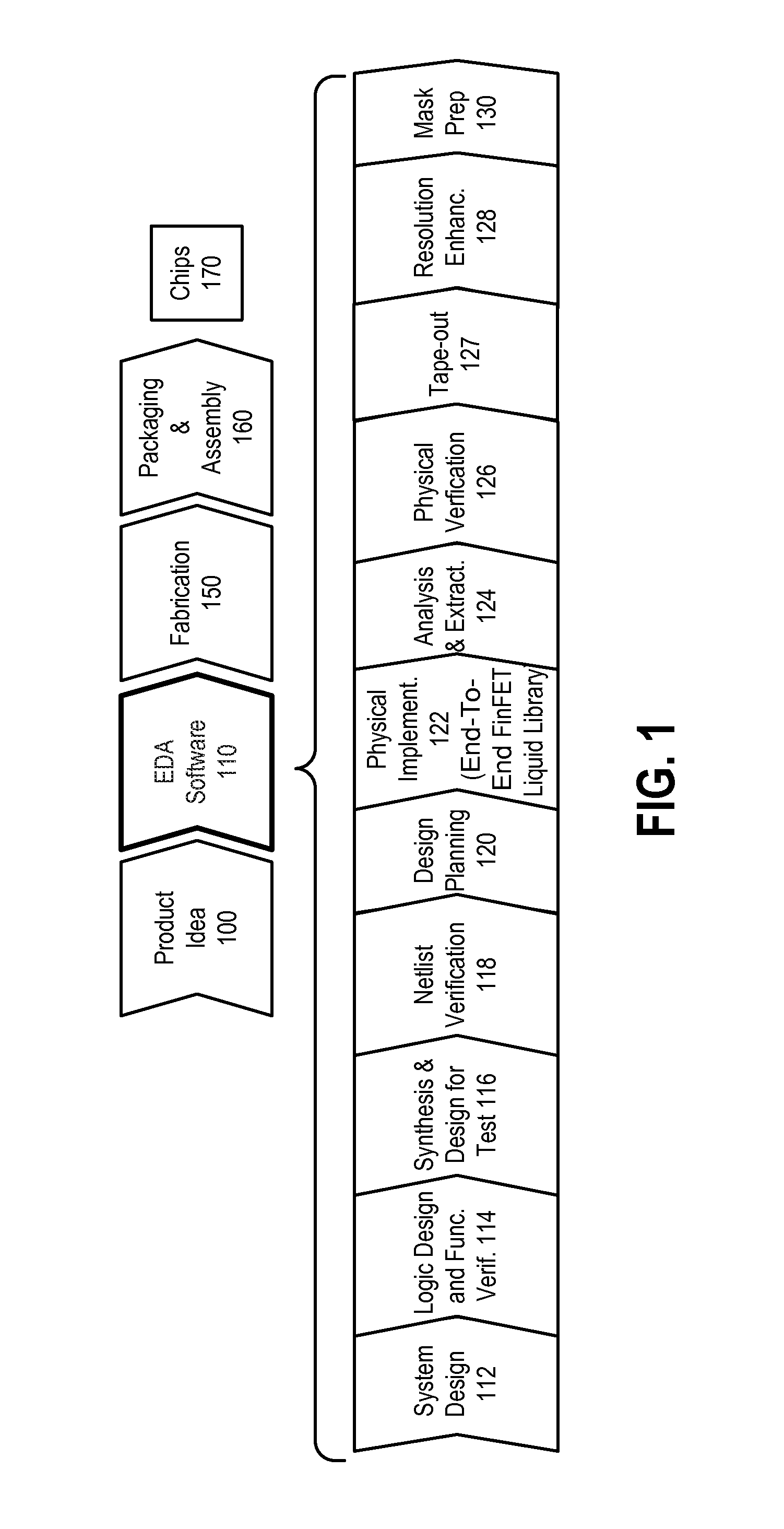
[0030]FIG. 1 is a simplified representation of an integrated circuit design flow. As with all flowcharts herein, it will be appreciated that many of the steps of FIG. 1 can be combined, performed in parallel or performed in a different sequence without affecting the functions achieved. In some cases a rearrangement of steps will achieve the same results only if certain other changes are made as well, and in other cases a rearrangement of steps will achieve the same results only if certain conditions are satisfied.

[0031]At a high level, the process of FIG. 1 starts with the product idea (block 100) and is realized in an EDA (Electronic Design Automation) software design process (block 110). When the design is finalized, the fabrication process (block 150) and packaging and assembly processes (block 160) occur, ultimately resulting in finished integrated circuit chips (result 170).

[0032]The EDA software design process (block 110) is actually composed of a number of steps 112-130, show...


PUM


Abstract

A finFET block architecture uses end-to-end finFET blocks in which the fin lengths are at least twice the contact pitch, whereby there is enough space for interlayer connectors to be placed on the proximal end and the distal end of a given semiconductor fin, and on the gate element on the given semiconductor fin. A first set of semiconductor fins having a first conductivity type and a second set of semiconductor fins having a second conductivity type can be aligned end-to-end. Interlayer connectors can be aligned over corresponding semiconductor fins which connect to gate elements.

Description

BACKGROUND[0001]1. Field of the Invention[0002]The present invention relates to integrated circuit devices, cell libraries, cell architectures and electronic design automation tools for integrated circuit devices, including finFET devices.[0003]2. Description of Related Art[0004]FinFET style transistors have been described in D. Hisamoto et al., IEDM, 1998; and N. Lindert et al., IEEE Electron Device Letters, p. 487, 2001. FinFETs have gained acceptance recently as the requirements of low power and compact layout have become more demanding. In CMOS devices, n-channel and p-channel blocks of transistors are placed in proximity, with insulators in between to prevent latch up, cross-talk and other problems.[0005]In the design of integrated circuits, standard cell libraries are often utilized. It is desirable to provide a finFET-based design architecture suitable for implementation of cells for a standard cell library, and for implementation of integrated circuits using finFET architect...

Claims


Application Information

Patent Timeline
Patent Type & Authority Patents(United States)
IPC IPC(8): H01L29/76
CPCG06F17/50H01L21/823821H01L27/0207H01L27/0924G06F17/5068H01L23/528H01L29/7843H01L2924/0002H01L2924/00G06F30/39
Inventor MOROZ, VICTORSHERLEKAR, DEEPAK D.
Owner SYNOPSYS INC
Why Eureka
Try Eureka