Manufacturing method of magneto-resistive element

a manufacturing method and magnetoresistive element technology, applied in nanoinformatics, instruments, record information storage, etc., can solve the problems of low mr ratio, deterioration of electrical characteristics of tmr element, and large amount of particles, and achieve high mr ratio

Active Publication Date: 2014-05-20
CANON ANELVA CORP
View PDF22 Cites 13 Cited by
  • Summary
  • Abstract
  • Description
  • Claims
  • Application Information

AI Technical Summary

Benefits of technology

[0020]According to the present invention, it is possible to provide a magneto-resistive element having a small number of particles and a high MR ratio.

Problems solved by technology

While generally a higher MR ratio can be obtained by the formation method of performing the RF sputtering of the MgO target, there is a problem that a lot of particles are generated in this method.
When the particles fall on a region corresponding to an MR element on a wafer, there arises a problem that electrical characteristics of the TMR element are deteriorated.
Meanwhile, in the method of forming the Mg layer and thereafter forming the MgO layer by the oxidation treatment, while particles are scarcely generated and this method is suitable for volume production compared to the method of performing RF sputtering of the MgO target, there is a problem that the MR ratio is small.

Method used


Image

  • Manufacturing method of magneto-resistive element
  • Manufacturing method of magneto-resistive element
  • Manufacturing method of magneto-resistive element

Examples


first embodiment

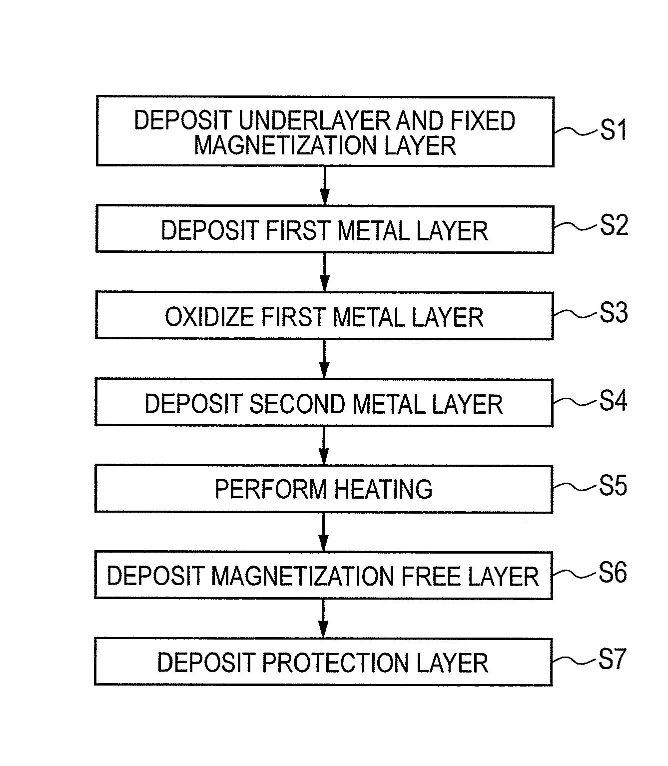
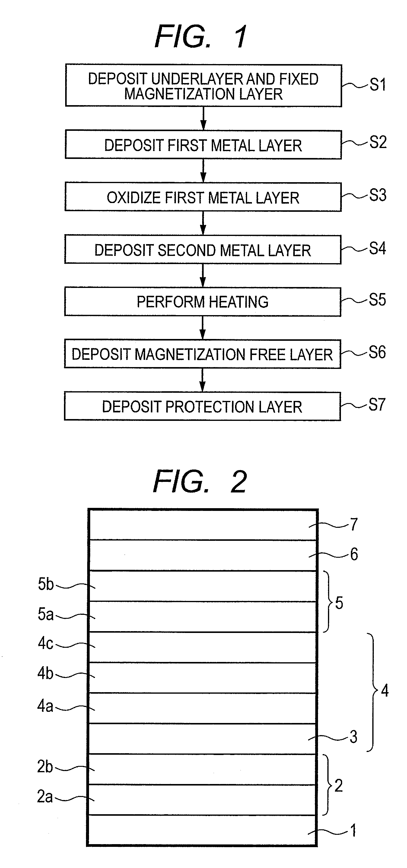
[0029]FIG. 1 is a flowchart explaining manufacturing steps of a TMR element according to the present embodiment. Further, FIG. 2 is a cross-sectional view schematically showing a configuration of the TMR element according to the present embodiment.

[0030]First, as shown in FIG. 1, an underlayer having a first underlayer 2a and a second underlayer 2b and a fixed magnetization layer 4 are deposited on a processing substrate 1 in step S1. For example, the underlayer configured with tantalum (Ta), hafnium (Hf), niobium (Nb), zirconium (Zr), titanium (Ti), molybdenum (Mo), tungsten (W), or the like, for example, is deposited having a thickness of approximately 0.5 to 5 nm on the processing substrate 1 as the first underlayer 2a of the multi-layered film. The second underlayer 2b containing at least one of elements such as nickel (Ni), iron (Fe), chromium (Cr), and ruthenium (Ru), for example, is deposited thereon in approximately 0.5 to 5 nm. An anti-ferromagnetic layer 3 configured with ...

example 1

[0054]A manufacturing method of a TMR element capable of obtaining a high MR ratio will be explained for the TMR element using the method of depositing the metal layer and thereafter forming the oxidation layer by oxidation treatment in the above described present embodiment.

[0055]In the present example, Mg was used for the first metal layer 5a and a first Mg layer was deposited in 1.2 nm as the first metal layer 5a. After that, the first Mg layer was oxidized and Mg (second Mg layer) was deposited in 0.4 nm as the second metal layer 5b. After that, TMR elements were fabricated and RA and MR ratios were measured for the case in which the substrate heating treatment (step S5 of FIG. 1) was performed at a temperature at which the second Mg layer evaporates (example 1) and the case of not performing the substrate heating treatment (comparison example 1). In the substrate heating treatment, a resistor was caused to generate heat and the substrate was heated by radiation. The substrate t...

second embodiment

[0063]In the present embodiment, the first metal layer 5a intentionally contains oxygen elements in the formation of the first metal layer 5a (the first metal layer 5a is doped with oxygen). That is, in the present embodiment, in the formation of the first metal layer 5a, oxygen gas is also introduced into the film deposition chamber and the first metal layer 5a is formed while oxygen is contained therein.

[0064]For example, when the first metal layer 5a is deposited by plasma sputtering, it is possible to cause the first metal layer 5a to contain oxygen atoms therein by adding oxygen to plasma formation gas in step S2 of FIG. 1. That is, a target of metal (e.g., Mg) which becomes the material of the first metal layer 5a is provided in the film deposition chamber, inert gas is introduced into the film deposition chamber and plasma is generated, and the first metal layer 5a is formed over the substrate 1 by plasma sputtering of the above target. In the above example, oxygen gas is int...


PUM

PropertyMeasurementUnit
thicknessaaaaaaaaaa
thicknessaaaaaaaaaa
thicknessaaaaaaaaaa

Abstract

The present invention provides a manufacturing method of a magneto-resistive element capable of obtaining a higher MR ratio, in a method of forming a metal oxide layer (e.g., MgO layer) by oxidation treatment of a metal layer (e.g., Mg layer). An embodiment of the present invention includes the steps of; providing a substrate having a first ferromagnetic layer; fabricating a tunnel barrier layer on the first ferromagnetic layer; and forming a second ferromagnetic layer on the tunnel barrier layer. The step of fabricating the tunnel barrier layer includes; the steps of; depositing a first metal layer on the first ferromagnetic layer; oxidizing the first metal layer; depositing a second metal layer on the oxidized first metal layer; and performing heating treatment on the oxidized first metal layer and the second metal layer at a temperature at which the second metal layer boils.

Description

CROSS-REFERENCES TO RELATED APPLICATIONS[0001]This application is a continuation application of International Application No. PCT / JP2010 / 073773, filed Dec. 28, 2010, which claims the benefit of Japanese Patent Application No. 2009-298254, filed Dec. 28, 2009. The contents of the aforementioned applications are incorporated herein by reference in their entireties.TECHNICAL FIELD[0002]The present invention relates to a manufacturing method of a magneto-resistive element exhibiting a high MR ratio.BACKGROUND ART[0003]A tunneling magneto-resistive (TMR) element has a structure in which a tunnel barrier layer is sandwiched between two ferromagnetic layers. When an external magnetic field is applied and the relative magnetization angle between the two ferromagnetic layers is changed, the tunneling conduction probability of an electron through the tunnel barrier layer is changed and the resistance of the TMR element is changed. Such a TMR element is applied to a read-out sensor part of a m...

Claims


Application Information

Patent Timeline
Patent Type & Authority Patents(United States)
IPC IPC(8): H01L21/00
CPCB82Y10/00G01R33/093B82Y25/00H01L43/12G11B5/3909G11B5/3906G01R33/098C08K3/22C08K2201/01H10N50/01G11B5/39
Inventor NISHIMURA, KAZUMASA
Owner CANON ANELVA CORP
Why Eureka
Try Eureka