Method and apparatus for fabricating silicon heterojunction solar cells

a solar cell and heterojunction technology, applied in the direction of sustainable manufacturing/processing, final product manufacturing, coatings, etc., can solve the problems of poor plasma density, limited control over the deposition rate, and deposition of semiconductor layers which lack uniformity, and achieve enhanced chemical vapor deposition, low process-induced damage, and high degree of uniformity

Active Publication Date: 2014-05-20
APPLIED MATERIALS INC
View PDF6 Cites 2 Cited by
  • Summary
  • Abstract
  • Description
  • Claims
  • Application Information

AI Technical Summary

Benefits of technology

[0008]The present invention generally comprises techniques for performing very high frequency plasma enhanced chemical vapor deposition (VHF-PECVD) of semiconductor thin-films having low process-induced damage and a high degree of uniformity.
[0010]Another embodiment of the present invention sets forth a method of fabricating a semiconductor layer. The method includes positioning one or more substrates on a substrate support disposed in a processing region in a plasma enhanced chemical vapor deposition (PECVD) apparatus, delivering a semiconductor-containing precursor gas and a dopant precursor gas into the processing region, and generating a very high frequency (VHF) plasma containing the semiconductor precursor gas and the dopant precursor gas in the processing region. A low-impedance current path between one or more walls of the PECVD apparatus and at least one of the shadow frame and the substrate support allows a current to flow therebetween when the VHF plasma is generated. The method further includes varying a ratio of the semiconductor precursor gas to the dopant precursor gas to form a graded semiconductor layer on the one or more substrates.

Problems solved by technology

However, conventional RF-PECVD processes often exhibit poor plasma density and limited control over deposition rate, resulting in the deposition of semiconductor layers which lack uniformity and exhibit unsatisfactory doping efficiencies.
Moreover, attempting to increase doping efficiencies of conventional RF-PECVD processes typically increases the degree of plasma, charge, and thermal damage in the resulting films, resulting in poor interface passivation characteristics and decreased device performance.

Method used


Image

  • Method and apparatus for fabricating silicon heterojunction solar cells
  • Method and apparatus for fabricating silicon heterojunction solar cells
  • Method and apparatus for fabricating silicon heterojunction solar cells

Examples


Embodiment Construction

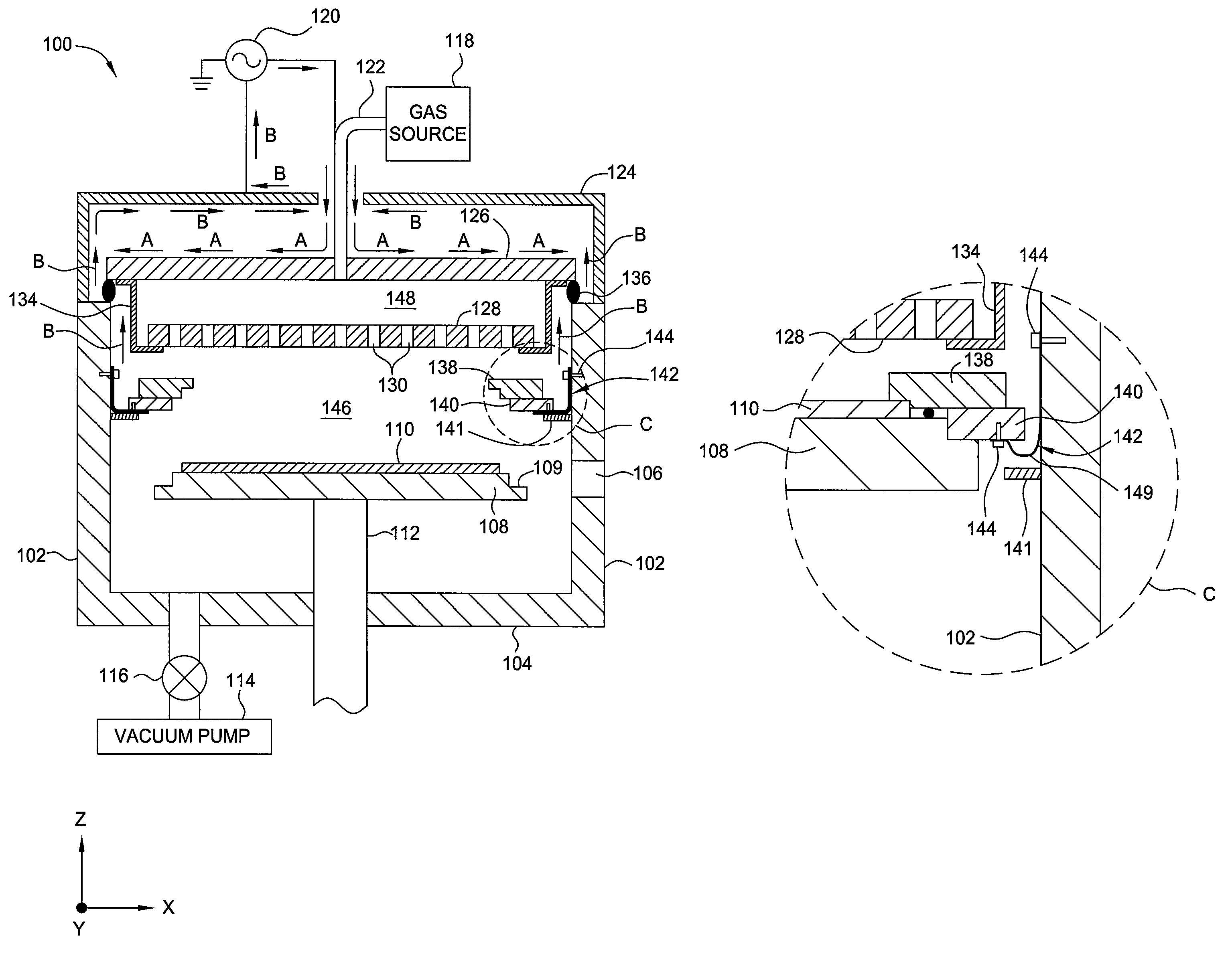
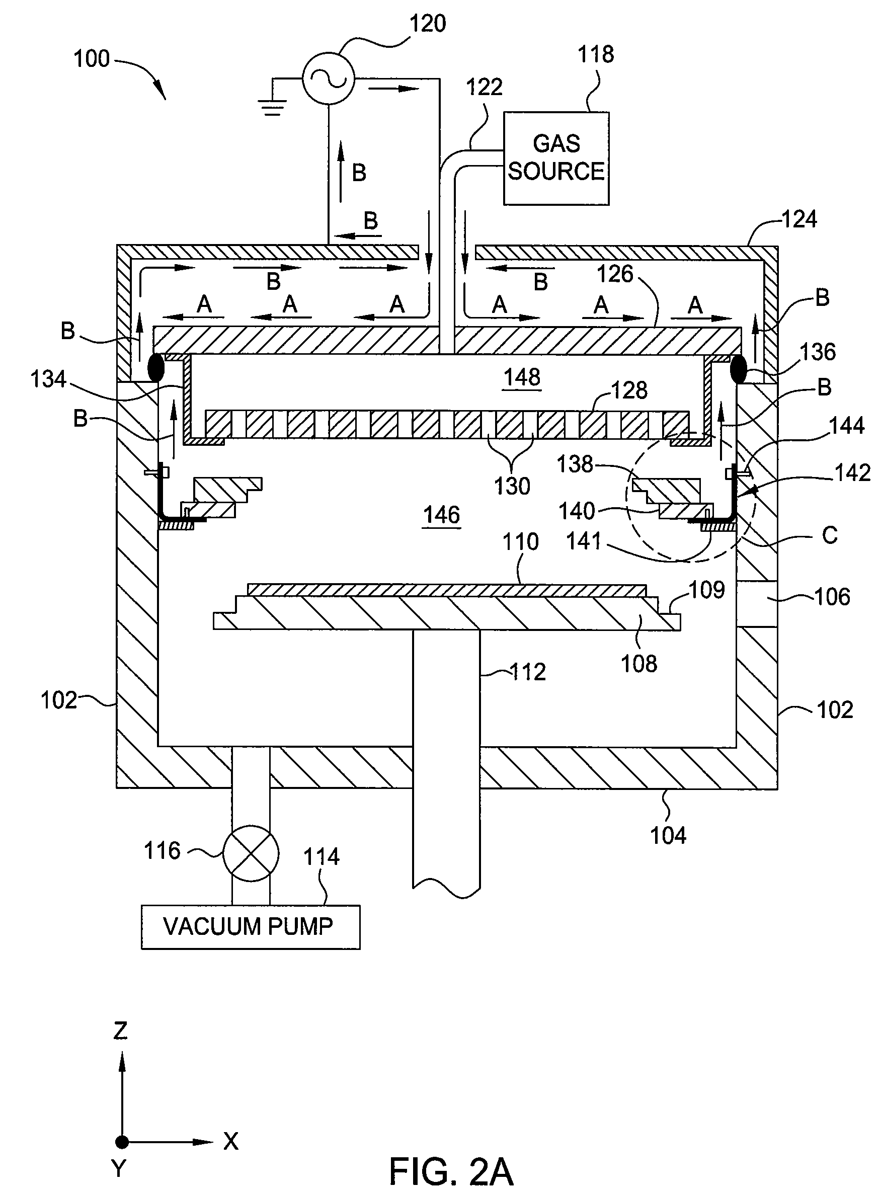
[0031]Embodiments of the present invention generally provide a processing system for deposition of semiconductor thin-films having low process-induced damage and a high degree of uniformity. In particular, it has been discovered that, in contrast to conventional radio frequency (RF) plasma enhanced chemical vapor deposition (PECVD) processes which utilize RF frequencies of less than about 30 MHz, semiconductor layers deposited via very high frequency (VHF) PECVD (approximately 30 to 300 MHz) display a low degree of plasma, charge, and thermal damage, resulting in films which exhibit superior interface passivation quality, increased doping efficiency, and an increase in overall heterojunction cell efficiency. Moreover, reduced deposition rates have improved thickness control and process repeatability. Finally, the unique process sequences used to fabricate the thin-film heterojunction layers allow for lower production costs and increased throughput (>2700 wafers / hour).
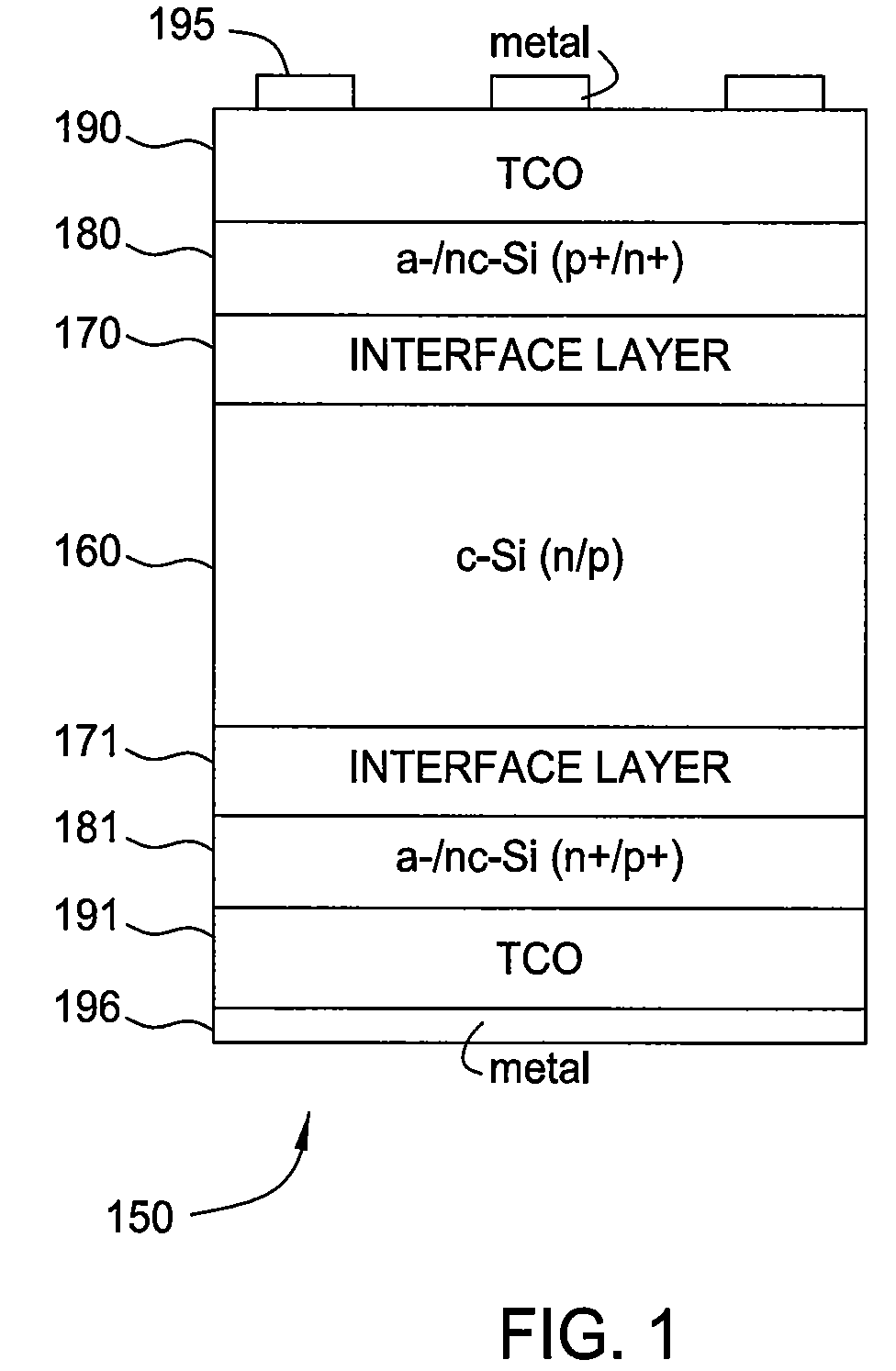
[0032]FIG. 1 is...


PUM

PropertyMeasurementUnit
frequencyaaaaaaaaaa
frequencyaaaaaaaaaa
frequencyaaaaaaaaaa

Abstract

A method for fabricating a semiconductor layer within a plasma enhanced chemical vapor deposition (PECVD) apparatus. The PECVD apparatus includes a plurality of walls defining a processing region, a substrate support, a shadow frame, a gas distribution showerhead, a gas source in fluid communication with the gas distribution showerhead and the processing region, a radio frequency power source coupled to the gas distribution showerhead, and one or more VHF grounding straps electrically coupled to at least one of the plurality of walls. The VHF grounding straps provide a low-impedance current path between at least one of the plurality of walls and at least one of a shadow frame or the substrate support. The method further includes delivering a semiconductor precursor gas and a dopant precursor gas and delivering a very high frequency (VHF) power to generate a plasma to form a first layer on the one or more substrates.

Description

CROSS-REFERENCE TO RELATED APPLICATIONS[0001]This application claims benefit of U.S. Provisional Patent Application Ser. No. 61 / 550,312, filed Oct. 21, 2011, which is herein incorporated by reference in its entirety.BACKGROUND OF THE INVENTION[0002]1. Field of the Invention[0003]Embodiments of the present invention generally relate to a plasma enhanced chemical vapor deposition (PECVD) method and apparatus.[0004]2. Description of the Related Art[0005]Photovoltaic (PV) or solar cells are devices which convert sunlight into direct current (DC) electrical power. A typical PV cell includes a p-type silicon wafer, or substrate, typically less than about 0.3 mm thick, with a thin layer of an n-type silicon material disposed on top of the p-type substrate. When exposed to sunlight, the p-n junction generates pairs of free electrons and holes. An electric field formed across a depletion region of the p-n junction separates the free holes from the free electrons, which may flow through an ex...

Claims


Application Information

Patent Timeline
Patent Type & Authority Patents(United States)
IPC IPC(8): H01L21/20
CPCH01L21/0257H01L21/0262Y02E10/547H01J37/32577H01J37/32082C23C16/44H01L21/02573H01L31/0747C23C16/24H01L21/02532C23C16/5096C23C16/4585H01L31/1804Y02P70/50
Inventor SHENG, SHURANZHANG, LINYUAN, ZHENGWANG, RONGPINGTSO, ALAN
Owner APPLIED MATERIALS INC
Why Eureka
Try Eureka