
Real-time in vivo radiation dosimetry using scintillation detectors

a detector and real-time technology, applied in the field of radiation dosimetry, can solve the problems of introducing unnecessary radiation-induced side effects, reducing the quality of life, and reducing the frequency of cancer recurrence, so as to achieve the effect of minimizing toxicities and not compromising quality of li

Active Publication Date: 2014-05-27
BOARD OF RGT THE UNIV OF TEXAS SYST
View PDF27 Cites 5 Cited by
  • Summary
  • Abstract
  • Description
  • Claims
  • Application Information

AI Technical Summary

Benefits of technology

The patent describes a system and method for measuring the dosage of radiation delivered to organs, critical structures and tumors during radiotherapy. This is achieved using a special detector made of multiple probes that can be placed in specific locations to monitor the dose in real-time. The detector is made up of a scintillating material that glows when exposed to radiation, an optical guide that carries the light, and a photodetector that converts the light into a measurable signal. The system can help to optimize treatment for maximum effectiveness and minimize risk of complications. Ultimately, the goal is to improve the quality of life for patients undergoing radiotherapy.

Problems solved by technology

Cancer recurrence is frequently the result of failed local control of treatment options.
Even with the best treatment planning modalities, there is no guarantee that the prescribed dose will be delivered exactly as planned.
At the same time, normal tissues may be shifted into the high dose region, introducing unnecessary radiation-induced side effects.
Presently there are no known available in vivo dosimetry systems that can sample both dose and dose rate fast enough to be suitable for real-time feedback.
However, there is no guarantee that the target will remain in the same place during the entire treatment period.
Even with the use of increasingly sophisticated radiotherapy techniques, it is difficult to determine if the dose has been delivered exactly as planned.
And, if not, it can be difficult to determine the degree to which the actual dose has deviated from the planned dose.
None of these detectors, aside from Si diodes, allows real-time measurement of dose rate, and none are water equivalent.
TLDs, ionization chambers and film do not allow in vivo dose measurements for various reasons (too bulky, slow response, safety concerns, etc.).
Even though Si diodes may have good spatial resolution, they suffer from strong energy dependence and are prone to dose perturbation depending on their orientation with respect to the beam (Beddar et al.
Although these devices can be used for in vivo dose measurements, they suffer from other drawbacks.
These include their non-water-equivalence and the required time delay of 5 to 6 minutes needed to retrieve the dose data between measurements.
Thus, one could not use these detectors to discriminate between individual beams in an IMRT or even a two-field proton therapy treatment.
It is clear that none of the detectors described above would satisfy the needs of the real-time in vivo dosimetry that would provide feedback fast enough to enable adaptive radiotherapy.
So far, several prototypes of plastic scintillation detectors have been proposed for applications in quality assurance, stereotactic radiosurgery, brachytherapy and general dosimetry but no scintillation detector to date can achieve real-time in vivo dosimetry.
A multiple-probe scintillation detector system has been recently developed for quality assurance but can only be used in phantom and not in patients.
Moreover the design of this detector system requires an acquisition time that is at least as a long as a radiotherapy treatment fraction, this design flaw prevents any real-time applications.

Method used


Image

  • Real-time in vivo radiation dosimetry using scintillation detectors
  • Real-time in vivo radiation dosimetry using scintillation detectors
  • Real-time in vivo radiation dosimetry using scintillation detectors

Examples


Embodiment Construction

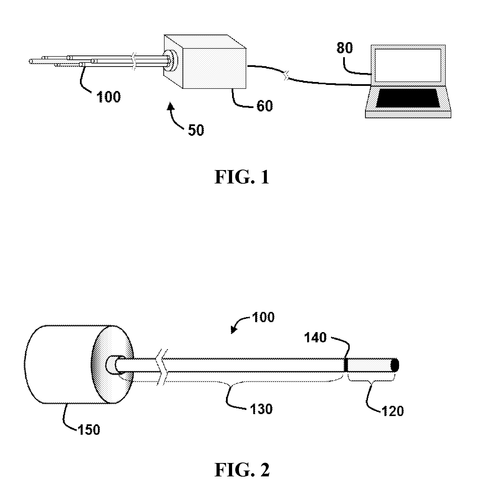
[0063]Referring initially to FIG. 1, an exemplary embodiment of a detector system 50 is configured to measure in vivo and in real time the amount of radiation delivered to a specific location within a patient's body. In this exemplary embodiment, detector system 50 comprises one or more detectors 100 configured to detect radiation, a CCD camera 60, and a data analyzer 80 (e.g., a computer) configured to analyze the radiation levels detected by the detectors 100. Other devices may be substituted for the CCD camera, including a CMOS detector, photmultiplier tube (PMT) array, photodiodes and / or avalanche photodiodes (APD).

[0064]As explained in more detail below, during operation the one or more detectors 100 may be coupled to a retention member that retains the detectors in a desired location within a patient. The patient may then be exposed to radiation (e.g., as part of radiation therapy for cancer) in the location where the detectors have been placed.

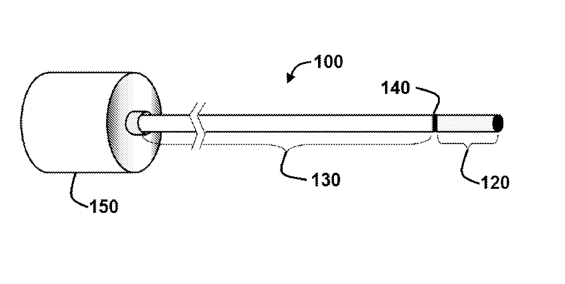
[0065]Referring now to FIG. 2, a...


PUM


Abstract

Apparatus and methods for measuring radiation levels in vivo in real time. Apparatus and methods include a scintillating material coupled to a retention member.

Description

[0001]This application is a national phase application under 35 U.S.C. §371 of International Application No. PCT / US2010 / 020366 filed Jan. 7, 2010, which claims priority to U.S. Provisional Patent Application No. 61 / 143,294, filed Jan. 8, 2009. The entire text of each of the above-referenced disclosures is specifically incorporated herein by reference without disclaimer.BACKGROUND OF THE INVENTION[0002]1. Field of the Invention[0003]The present invention relates generally to the fields of radiation dosimetry. More particularly, it concerns the use of scintillating detectors to detect radiation levels in vivo.[0004]2. Description of Related Art[0005]Cancer recurrence is frequently the result of failed local control of treatment options. Reducing the likelihood of recurrence in radiotherapy means giving the largest possible radiation dose to the tumor region while limiting the dose to healthy organs at risk for treatment-induced toxicity. Even with the best treatment planning modalitie...

Claims


Application Information

Patent Timeline
Patent Type & Authority Patents(United States)
IPC IPC(8): G01T1/20
CPCA61N2005/1072A61N5/1071G01T1/161A61N5/1048G01T1/023
Inventor BEDDAR, A. SAMBRIERE, TINA MARIEARCHAMBAULT, LOUIS
Owner BOARD OF RGT THE UNIV OF TEXAS SYST
Learn More