Method and apparatus for the filtration of biological samples

a biological sample and filtration technology, applied in the field of sample preparation modules and methods, can solve the problems of bringing the process to a standstill, vanishingly small flux, and increased cost and large hold-up volumes, and achieve high retentate recovery or permeate recovery, low processing time, and high membrane area ratio

Inactive Publication Date: 2014-06-10
SPF INNOVATIONS
View PDF66 Cites 40 Cited by
  • Summary
  • Abstract
  • Description
  • Claims
  • Application Information

AI Technical Summary

Benefits of technology

[0017]It has been discovered that the use of separation modules suitable for sample-preparation having long thin channels with relatively large ratios of channel membrane area to channel void volume, to volume of a sample feed reservoir, and to volume of the feed sample, can yield relatively fast, high-conversion, low hold-up-volume, single-pass TFF (SPF) separations that can be driven with low pressures.
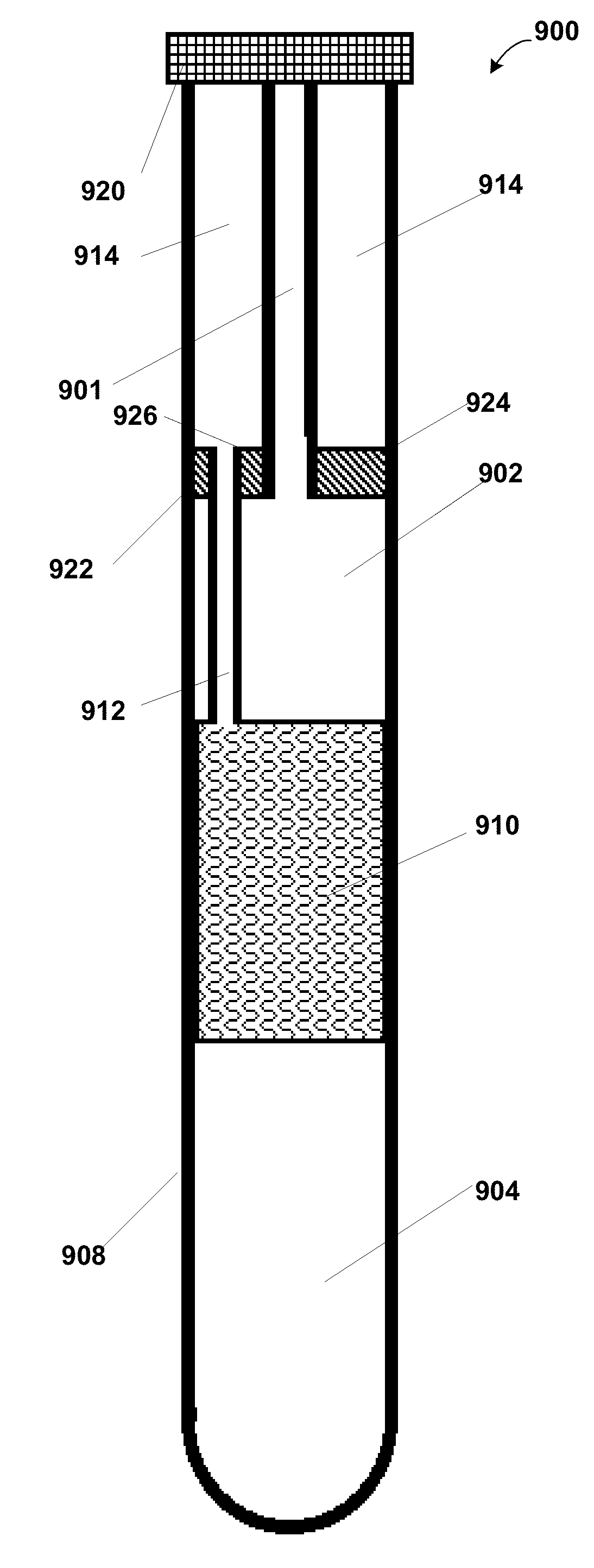
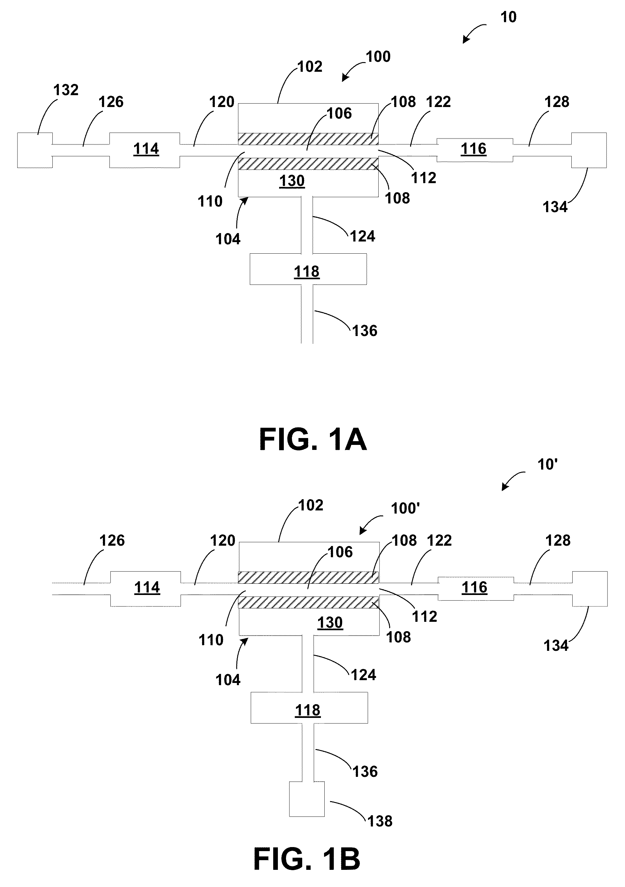
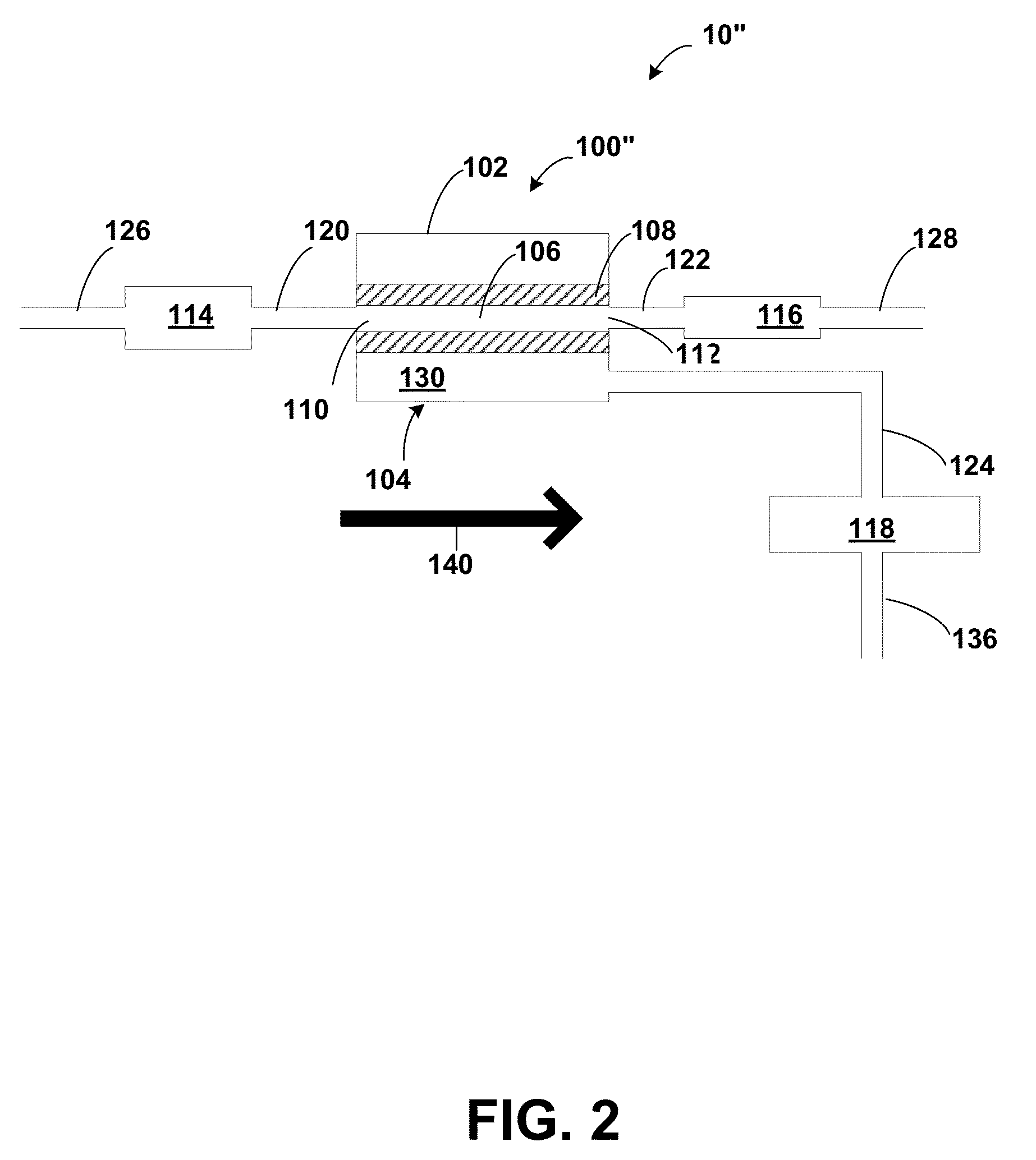
[0018]In accordance with one aspect of the present invention, a separation module for the filtration of a liquid sample includes a separation element having at least one flow channel with an inlet, an outlet and a surface including an ultrafiltration membrane. The module further includes a feed reservoir fluidly coupled to the channel inlet, a retentate reservoir fluidly coupled to the channel outlet, a permeate reservoir fluidly coupled to the separation element. The ratio of the membrane area of the separation element to the volume of the feed reservoir is greater than about 2 cm−1. Such a module is capable of processing a sample in a single-pass mode while providing a high conversion with a relatively low hold up volume. The module yields high reliable flux and high conversion without the need of recirculation loops, numerous valves and intermediate pumps.

Problems solved by technology

Low flux can result in long filtration times or large modules, resulting in increased cost and large hold-up volumes (i.e., the volume including the retained species remaining in the module).
In the absence of counter measures the accumulation of “polarized” particles or solutes results in vanishingly small fluxes and bringing the processes to a stand-still.
Because higher tangential velocities produce higher fluxes, the conventional practice of TFF calls for the use of high velocities in the flow channels, which in turn result in very high feed rates.
These high feed rates result in low conversion, typically less than 10% and often less than 5%.
The application of conventional TFF processes to sample preparation at the analytical scale is generally believed not to be practical due to the complications in the use of pumps and recirculation loops which are normally required for TFF processes.
As a result, UF separations at these scales are practiced almost exclusively in a “dead-ended” mode, resulting in an inherently low flux due to concentration polarization.
However, while these have become the dominant format for analytical scale UF, they typically require centrifuges capable of exposing the UF device to accelerations as high as 14,000 g. Furthermore, in spite of these accelerations, many separations still require long times, often one hour or more.
Finally, the recovery of the retentate presents special difficulties in these approaches since it may be spread as a thin film over the surface of the membrane.
The main reasons are that existing MF / UF devices require a centrifuge, take a considerable amount of time to process samples, and in the case of whole blood, they do not work at all.
Furthermore, centrifugation is costly and makes it difficult to process multiple samples at the same time.
None of the prior art devices and methods provide rapid, controlled conversion without the use of numerous venting valves, recirculation loops and pumps in addition to simple construction and operation.
Furthermore, while ultrafiltration membranes are capable of separating small molecule drugs and hormones from large and abundant species (e.g. albumin, among others), conventional centrifugal UF devices are not capable of processing whole blood.
Although the existing (UF) centrifugal devices are capable of fractionating plasma or serum, it takes a very long time to fractionate solutions with protein concentrations greater than about 0.5%, far exceeding the fast turn-around demands of a clinical laboratory.
For that reason, centrifugal UF devices have found little use in clinical laboratories for free drug / hormone assays.
Also, with the use of UF membranes such a device would allow the collection of a fraction containing only free drugs / hormones, thereby enabling direct determination which is difficult or not even possible in a many clinical settings.

Method used


Image

  • Method and apparatus for the filtration of biological samples
  • Method and apparatus for the filtration of biological samples
  • Method and apparatus for the filtration of biological samples

Examples


examples 1a and 1b

[0133]The following two examples illustrate experiments in which pressure sources were used to drive the filtration using the instrumented sample preparation system similar to system 200 of FIG. 5A.

Test Solutions

[0134]A bovine serum albumin (BSA) solution was prepared at a concentration of 10 mg / ml in 0.025 M Tris-HCl Buffer adjusted to pH 7.6. All experiments were conducted at room temperature. The BSA was obtained from Sigma-Aldrich, catalog number A-3294.

[0135]SPF Modules

[0136]SPF modules 190 were made with separation elements 194 comprising hollow fiber membranes. Hollow fiber membranes were polysulfone with a 10,000 MWCO. The separation elements 194 were constructed by potting the hollow fiber membranes into a ⅛″ ID clear Tygon™ tubing with a 5-minute epoxy. Modules were made with varying lengths and varying number of polysulfone hollow fiber membranes. Separation elements had two permeate ports (the second port not shown) to allow effective flushing of the permeate compartment...

examples 2a , 2b and 2c

EXAMPLES 2A, 2B AND 2C

[0167]The following examples compare SPF UF processing with 600 μm hollow fiber (HF) Membrane to prior art centrifugal devices to demonstrate the slower performance of prior art centrifuge techniques for processing of laboratory scale samples. Examples 2A and 2B provide data on a method of processing of a 3-volume embodiment of the present invention utilizing pressure sources to drive the single-pass ultrafiltration. These examples illustrate the concentration of 10 mg / ml BSA using 10,000 MWCO hollow fibers with lumen diameter of about 600 μm and 155 cm long. In contrast, Example 2C provides data on a method of the prior art utilizing a centrifugal device, Microcon 30, manufactured by Millipore Corp., Billerica Mass., USA.

[0168]In examples 2A and 2B, the separation element used in the SPF module comprised a single hollow fiber membrane, having a membrane area of about 29 cm2. The feed stream comprised of about 5 ml of BSA solution (exact weight shown in Table 4...

examples 3 and 4

[0174]The descriptions of the methods and modules used in examples 1 and 2 apply to examples 3 and 4, except that vacuum sources were used to drive the permeation instead of positive pressure sources. The test set up was accordingly modified as described below. The procedure outlined in examples 1 and 2 was followed with minor adjustments to account for the use of vacuum sources instead of pressure sources.

[0175]Test Set-Up

[0176]A system similar to system 230 was used for examples 3 and 4 as shown in FIG. 5B. A vacuum pump 232 was used as the vacuum source coupled to the permeate port. The vacuum pump 232 was capable of generating vacuums exceeding 29 in-Hg. The feed port 126 was vented to atmospheric pressure, and therefore the TMP was about 14.7 psi. The retentate pressure, or more precisely, the TCP, was finely regulated by means of the gravity siphon 240, whereby the height of the column of water 242 essentially determines the TCP, the TCP being directly proportional to the heig...


PUM

PropertyMeasurementUnit
volumesaaaaaaaaaa
volumeaaaaaaaaaa
volumeaaaaaaaaaa

Abstract

A separation module and method are disclosed for processing a liquid sample and providing high conversion by operating a single-pass tangential-flow process without a recirculation loop. In one embodiment, the separation module includes three reservoirs and has at least one long, thin channel with a large ratio of channel membrane area to: channel void volume; volume of a sample feed reservoir; and volume of the feed sample. In another embodiment, the separation module includes an external feed reservoir, an external retentate reservoir fluidly and a first vacuum source adapted to apply a first vacuum to the separation element disposed within the housing. The single-pass TFF separation element and single-pass process provides high conversion while operating with relatively low pressure sources. Certain embodiments disclosed herein can be used for the separation of blood.

Description

RELATED APPLICATIONS[0001]This application is a Continuation in part of patent application Ser. No. 12 / 371,611 filed Feb. 15, 2009, now U.S. Pat. No. 8,231,788, granted Jul. 31, 2012, and claims benefit of 61 / 234,286, filed Aug. 15, 2009, and is a continuation of application Ser. No. 11 / 615,031 filed Dec. 22, 2006 now U.S. Pat. No. 7,510,654, granted Mar. 31, 2009 and which claims the benefit of U.S. Provisional Application No. 60 / 755,009, filed Dec. 29, 2005, and U.S. Provisional Application No. 60 / 754,813, filed Dec. 29, 2005, which applications are hereby incorporated herein by reference in their entirety.STATEMENTS REGARDING FEDERALLY SPONSORED RESEARCH[0002]This invention was made with government support under Grant Number GM-079876 awarded by the National Institutes of Health. The government has certain rights in the invention.BACKGROUND OF THE INVENTION[0003]1. Field of the Invention[0004]The invention relates generally to a sample preparation modules and methods and more spe...

Claims


Application Information

Patent Timeline
Patent Type & Authority Patents(United States)
IPC IPC(8): B01D35/00B01D61/00B01D63/00B01D41/00B01D11/00
CPCB01L2400/049B01D63/10B01D63/02B01D2319/022G01N2001/4088B01D61/14B01L3/50255B01L2300/0858B01D61/145B01D2315/16B01D61/16B01D63/066B01D2313/08B01D2315/14G01N1/4005B01L2300/0838B01L2200/12B01D61/18B01D2311/04B01D61/147B01D2317/022B01D61/22B01L2300/0829B01D2311/2649B01D2311/14B01D2311/25
Inventor BONNER, ALEX G.DE LOS REYES, GASTON
Owner SPF INNOVATIONS
Why Eureka
Try Eureka