

Process for oligomerizing dilute ethylene
a technology of oligomerization and dilute ethylene, which is applied in the direction of catalyst regeneration/reactivation, physical/chemical process catalysts, metal/metal-oxide/metal-hydroxide catalysts, etc., can solve the problems of ethylene recovery not economically justified by gas recovery systems and ethylene is little used as oligomerization feedstock
- Summary
- Abstract
- Description
- Claims
- Application Information
AI Technical Summary
Benefits of technology
Problems solved by technology
Method used
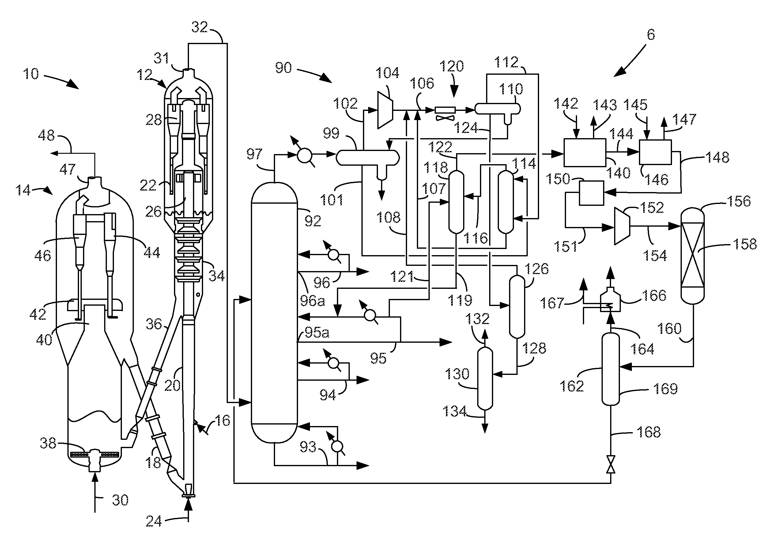
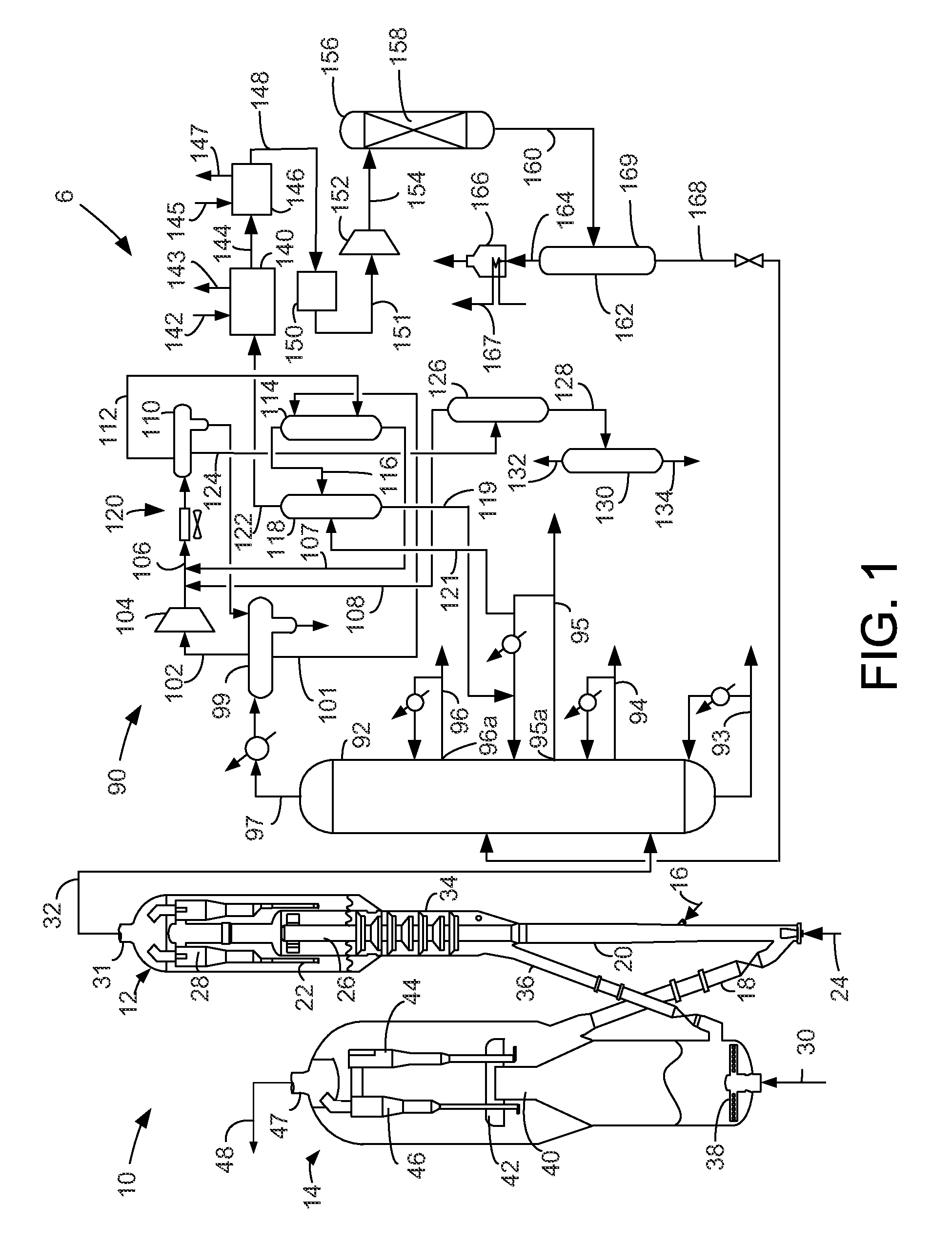
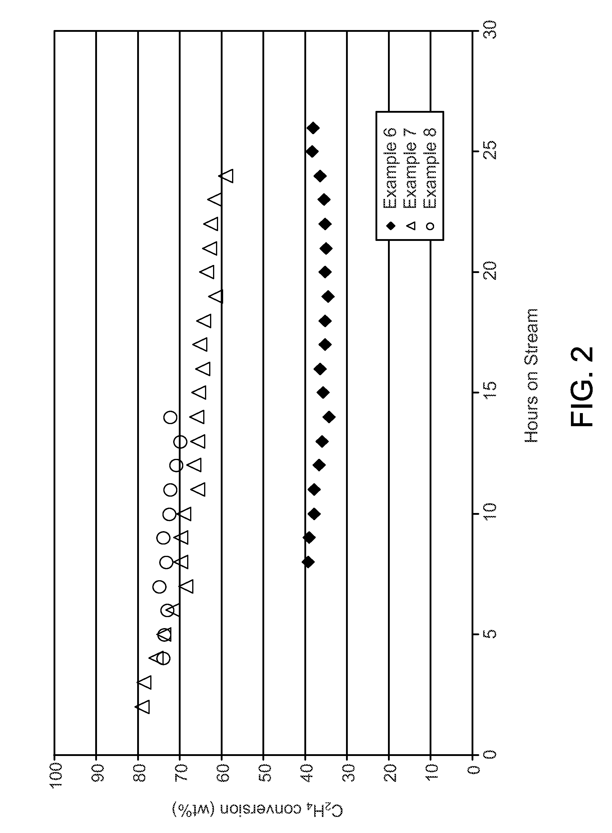
Image

Examples
example 1
[0052]A nickel and tungsten on an amorphous silica-alumina oil-dropped spherical base was synthesized via the procedures given hereinabove for the alternative catalyst of the present invention. The metals comprised 1.5 wt-% nickel and 11 wt-% tungsten of the catalyst. The spherical bases had diameters of 3.175 mm. The catalyst had a silica-to-alumina ratio of about 3, a density of 0.641 g / mL and a surface area of 371 m2 / g.
example 2
[0053]An extruded amorphous silica-alumina was synthesized by combining an amorphous silica-alumina having a silica-to-alumina ratio of about 2.6 provided by CCIC, and pseudo-boehmite provided under the Catapal trademark in a weight ratio of 85-to-15. The pseudo-boehmite was peptized with nitric acid before mixture with the amorphous silica-alumina. A surfactant provided under the Antarox trademark and water in sufficient quantity to wet the dough were added to the mixture. The catalyst dough was extruded through 1.59 mm openings in a cylindrical die plate and broken into pieces prior to calcination at 550° C. The finished catalyst consisted of 85 wt-% silica-alumina and 15 wt-% alumina, had a silica-to-alumina ratio of 1.92 and had a surface area of 368 m2 / g.
example 3
[0054]Of Ni(NO3)2.6H2O, 3.37 grams was dissolved in 32.08 grams of deionized water. The nickel solution was contacted with the extruded amorphous silica-alumina of Example 2 by adding the nickel solution in fourths and shaking vigorously between additions. A light green extrudate resulted. The nickel metal was then converted to the oxide form by drying the extrudates at 110° C. for 3 hours, then calcining by ramping to 500° C. at 2° C. / min and holding at 500° C. for 3 hours before cooling to room temperature. The light gray extrudates were found to contain 1.5 wt-% nickel.
PUM
| Property | Measurement | Unit |
|---|---|---|
| pressure | aaaaa | aaaaa |
| temperature | aaaaa | aaaaa |
| temperature | aaaaa | aaaaa |
Abstract
Description
Claims
Application Information