Forwarding node in a wireless communication system

a wireless communication system and forwarding node technology, applied in the field of relay or repeater node, can solve the problems of limited gain that can be applied in such a repeater, prone to self-interference of on-frequency repeater, and limited maximum gain, so as to achieve the effect of improving performan

Active Publication Date: 2014-06-10
TELEFON AB LM ERICSSON (PUBL)
View PDF8 Cites 37 Cited by
  • Summary
  • Abstract
  • Description
  • Claims
  • Application Information

AI Technical Summary

Benefits of technology

[0011]It is an object of the invention to provide a relay and / or repeater node with improved performance under varying conditions.
[0018]By enabling adaptive switching between on-frequency operation and receive and transmitting on orthogonal resources for the relay / repeater node the invention ensures that the repeater function can be performed without duplex loss whenever possible, that is, when an on-frequency repeating is feasible. At the same time, higher gain can be achieved when this is desirable, to enable supporting repeater node to receiver node links with a higher path loss, or Signal to Interference Ratio (SIR). In addition, switching to the frequency translating mode can enable improving the reception performance of the relay / repeater node through the enhanced signal to interference ratio as self-interference can not be cancelled perfectly in the on-frequency mode.
[0019]Hence, a main benefit of this adaptive hybrid operation between on-frequency repeater operation and either of frequency translating repeater or a relay is that the spectral efficiency offered by on-frequency repeater can be used, whereas still operating in situations where high gain operation is occasionally required.
[0020]Another benefit is that when the relay / repeater node may experience a low SNR at receiving, the switching from the normal spectral efficient on-frequency operation to the mode where reception and transmission from the relay occur on orthogonal resources enables increased receiver sensitivity for the repeater as the feedback signal occur on another non-interfering resource.
[0021]In a preferred embodiment, the mode switching unit is arranged to switch between a first mode wherein the transmit antenna side utilizes the same resource as the receive antenna side and a second mode wherein the transmit antenna side utilizes a different resource from the receive antenna side. The use of different resources will reduce the self-interference from the transmitting side to the receiving side. Preferably, in the second mode, the transmit antenna side utilizes a resource that is substantially orthogonal to the resource used by the receive antenna side, as this will minimize the self-interference.
[0024]As an added feature, the mode switching unit may be arranged to switch to a third mode when the required amplification gain is above a second threshold which is higher than the first threshold. This will enable a predefined structure of different translation modes, depending on which mode provides the best protection against self-interference.

Problems solved by technology

On the other hand, an on-frequency repeater is prone to self-interference since the same signal is received and transmitted at virtually the same time.
Therefore, the gain that can be applied in such a repeater is limited to a level that will not cause excessive self-interference.
Even with such measures to reduce self-interference, the maximum gain is limited.
The on-frequency repeater is an attractive solution to come to terms with the duplex loss seen for relays and frequency translating repeaters, but is often inadequate when the repeater receives a weak signal and needs to amplify the signal and communicate to a distant receiver to which the path loss is high.

Method used


Image

  • Forwarding node in a wireless communication system
  • Forwarding node in a wireless communication system
  • Forwarding node in a wireless communication system

Examples


Embodiment Construction

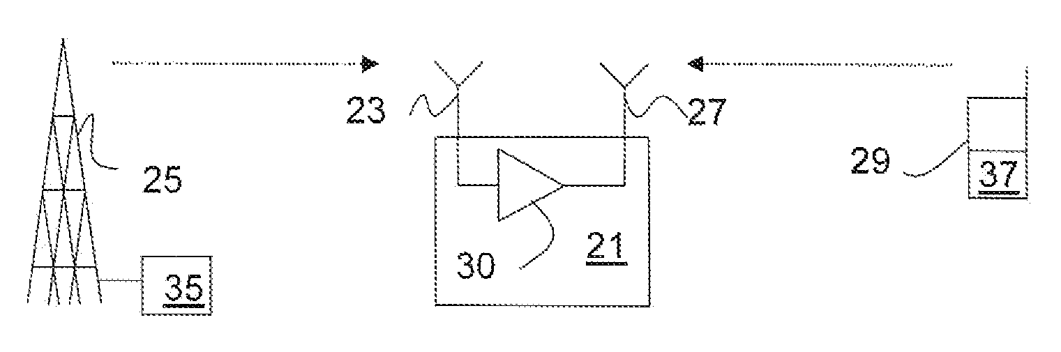
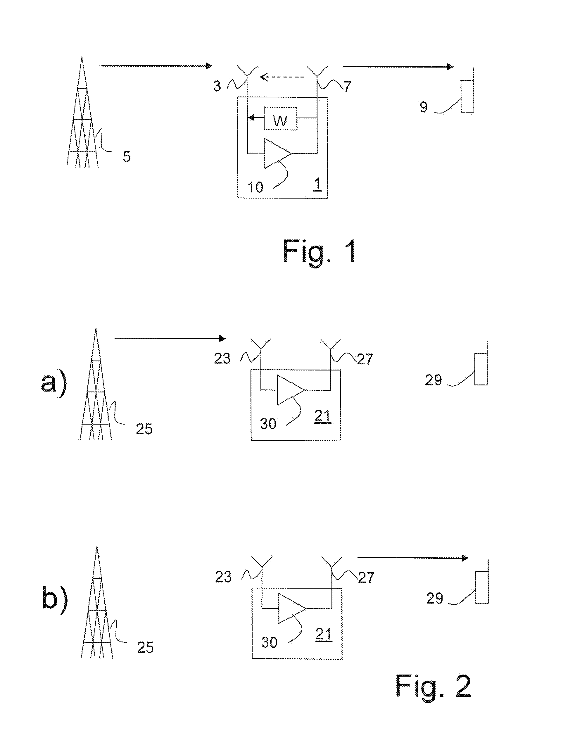
[0034]FIG. 1 illustrates an on-frequency repeater function, that is, the repeater receives and transmits on the same resource at substantially the same time, hence causing self interference from the output to the input, although in practice there will always be a small delay. The repeater 1 comprises a receive antenna 3 arranged to receive a signal from a base station 5 and a transmit antenna 7 arranged to forward the signal to a mobile terminal 9. An amplifier 10 provides a gain between the receive antenna 3 and the transmit antenna 7. The signal is forwarded on the same resource on which it was received. This means that the repeater 1 uses the same frequency, non-orthogonal coding etc. and forwards the signal immediately upon receiving it.

[0035]Such repeaters are prone to self-interference, and are therefore typically designed so that the transmit and receive antennas are isolated from each other to the extent possible. As discussed above self-interference cancellation methods bas...


PUM


Abstract

The invention relates to a relay or repeater node (21) for use in a wireless communications system said node comprising a receive antenna (23) for receiving a signal through a wireless connection, an amplifier (30) for amplifying the signal and a transmit antenna (27) for forwarding the amplified signal, said node further comprising a mode switching unit (31) for switching between at least a first and a second mode of operation of the node in dependence of an amplification gain requirement. This enables optimization of the node for varying conditions in the network.

Description

TECHNICAL FIELD[0001]The present invention relates to a relay or repeater node for use in a cellular communications system and a method of operating such a node.BACKGROUND AND RELATED ART[0002]As more and more communication is performed in wireless / cellular communication systems, the requirements on such systems are constantly increasing. Such requirements relate both to increased coverage and support of higher data rates, or preferably a combination of both.[0003]To enhance coverage and data rate a forwarding node, such as a repeater or a relay, is often used. Such forwarding nodes typically receive the signal and amplify it before transmitting it to the receiver. The benefit of using repeaters and relays stems primarily from that splitting a long distance in two hops allows increased data rate on each link as well as End-To-End total data rate.[0004]The distinction between the repeaters and relays is not entirely clear cut. Often, the term repeater is used to denote a simple, low ...

Claims


Application Information

Patent Timeline
Patent Type & Authority Patents(United States)
IPC IPC(8): H04B7/14H04B3/36
CPCH04W16/02H04W16/26H04B7/15535
Inventor LARSSON, PETERJOHANSSON, NIKLAS
Owner TELEFON AB LM ERICSSON (PUBL)
Why Eureka
Try Eureka