Quartz-based disk resonator gyro with ultra-thin conductive outer electrodes and method of making same

a gyroscope and ultra-thin technology, applied in the field of gyroscopes and also to mems structures, can solve the problems of high electrical impedance, low quality factor, and degraded q of the resonator, and achieve the effect of reducing the chance of micromasking defects in the trenches, and reducing the quality factor

Active Publication Date: 2014-07-01
HRL LAB +1
View PDF211 Cites 19 Cited by
  • Summary
  • Abstract
  • Description
  • Claims
  • Application Information

AI Technical Summary

Benefits of technology

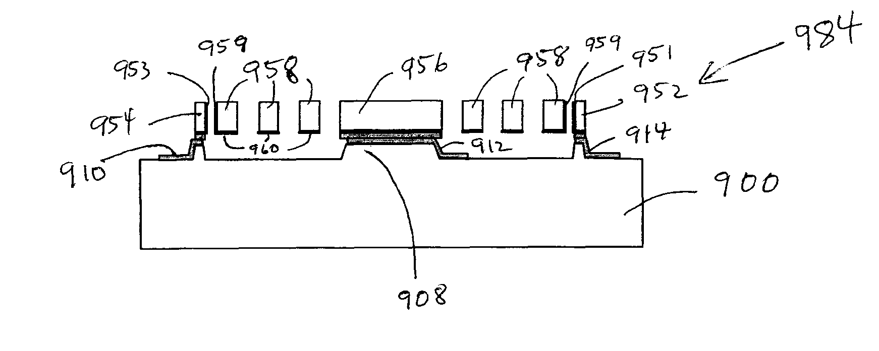
[0031]In another aspect of this embodiment the base further comprises a first raised area and metal deposited on the first raised area for connecting to the central pillar, and a second raised area and metal deposited on the second raised area for electrical connection and bonding to the electrode.
[0032]In yet another aspect of this embodiment the first raised area has a height of about 3-4 μm and the second raised area has a height of about 3-4 pan.
[0033]In another aspect this embodiment further comprises a conductive film on the surface of the resonant structure, the outer edge of the resonant structure, the central pillar, and a top surface and an inner wall of the electrode, wherein the inner wall of the electrode faces the outer edge of the resonant structure. The conductive film may be an Atomic Layer Deposition metal and be less than 100 nanometers thick. The conductive film may comprises one of Pt, Ru, Rh, Pd, Re, or Ir.

Problems solved by technology

A disadvantage of the conductive coating is that the Q of the resonator is degraded.
Also this the process of conductive coating within the deep trenches introduces a chance of micromasking defects being created in the trenches.
However, a problem with silicon-based resonators is that they have high electrical impedances and low quality factors.
A rough or damaged surface increases a resonator's surface / volume ratio, which in turn increases dissipation of oscillation energy.
These processes are only slightly conformal (with sputtering being the best) on high-aspect-ratio structures, as these processes generally coat structures along a line-of-sight from the source, resulting in non-uniform thickness metal films which introduce stress gradients over temperature, degrading Q. Chemical Vapor Deposition (CVD) processes are more conformal than sputtering, electron beam evaporation, or thermal evaporation, but are not able to produce substantially pure metal films, desired for high conductivity.
Another problem with sputtering, electron beam evaporation, or thermal evaporation processes is the films generally form grain structures due to the kinetics of the grow process.
Slippage between these grains during mechanical bending results in energy loss, degrading Q. Also, the grain structure limits the minimum thickness which can be applied in order to obtain electrical continuous films, also degrading Q as well as resonate frequency.
The thickness of the metal film can not be controlled on the monolayer scale using these processes.
However, a disadvantage of this prior art quartz resonator is that Q of the resonator is significantly degraded, when the conductive coatings are applied to all of the resonator portions.

Method used


Image

  • Quartz-based disk resonator gyro with ultra-thin conductive outer electrodes and method of making same
  • Quartz-based disk resonator gyro with ultra-thin conductive outer electrodes and method of making same
  • Quartz-based disk resonator gyro with ultra-thin conductive outer electrodes and method of making same

Examples


Embodiment Construction

[0070]In the following description, numerous specific details are set forth to clearly describe various specific embodiments disclosed herein. One skilled in the art, however, will understand that the presently claimed invention may be practiced without all of the specific details discussed below. In other instances, well known features have not been described so as not to obscure the invention.

Bilayer High Q Coating and Method

[0071]FIG. 7 is a flowchart of a method 710 of forming an ultra-thin, highly conformal and highly conductive bilayer dielectric / metal coating. In operation 712, a dielectric substrate having at least one resonate structure defined thereon is provided. The dielectric substrate could be, for example, quartz, fused quartz, fused silica, or any other dielectric having desired properties.

[0072]In operation 714 the dielectric substrate is sealed in a vacuum chamber suitable for Atomic Layer Deposition processes. In operation 716, an ALD dielectric film is formed on ...


PUM


Abstract

A disk resonator gyroscope includes a quartz base, a quartz resonator disk having a central pillar connected to the base, the quartz resonator disk having a surface facing the base and having plurality of circumferential slots in the surface of the quartz resonator disk around the central pillar, and an electrode comprised of quartz and connected to the base outside of an outer edge of the resonator disk.

Description

CROSS-REFERENCE TO RELATED APPLICATIONS[0001]This application is a continuation in part of U.S. patent application Ser. No. 12 / 179,579, filed Jul. 24, 2008 now abandoned and entitled “ALD METAL COATINGS FOR HIGH Q MEMS STRUCTURES”, which is incorporated herein by reference as though set forth in full and also claims the benefit under 35 U.S.C. §119(e) of U.S. Provisional Application No. 61 / 082,125 filed Jul. 18, 2008 and entitled ALD Metal Coatings for High Q MEMS Resonators, U.S. Provisional Patent Application No. 60 / 962,176, filed Jul. 25, 2007 and entitled “ALD METAL COATINGS FOR HIGH Q MEMS RESONATORS”, and U.S. Provisional Patent Application No. 60 / 973,703, filed Sep. 19, 2007 and entitled “ALD METAL COATINGS FOR HIGH Q MEMS STRUCTURES”, which are incorporated herein by reference as though set forth in full.[0002]This application is related to U.S. patent application Ser. No. 11 / 458,911, filed Jul. 20, 2006 and entitled “DISC RESONATOR GYROSCOPES,” which is incorporated herein ...

Claims


Application Information

Patent Timeline
Patent Type & Authority Patents(United States)
IPC IPC(8): H03H9/02G01C19/00H03H9/24
CPCH03H2009/02283H03H3/0072H03H9/2436H03H9/02H03H9/24H03H9/02244G01C19/00H03H2009/02496H03H9/0552H03H9/1057G01P1/00G01C19/5684
Inventor KUBENA, RANDALL L.CHANG, DAVID T.LARSON, ROBERT L.
Owner HRL LAB
Why Eureka
Try Eureka