Fluid system for supplying a device with highly pure liquid

a technology of flue gas and liquid supply, which is applied in the direction of filtration separation, separation process, coupling, etc., can solve the problems of high installation cost, temperature loss, and increased heating of the permeate, and achieves low investment and operating cost, facilitates assembly and possibly disassembly of the flow block, and high hygienic standard

Active Publication Date: 2014-07-29
VIVONIC GMBH
View PDF14 Cites 25 Cited by
  • Summary
  • Abstract
  • Description
  • Claims
  • Application Information

AI Technical Summary

Benefits of technology

[0016]It is the object of the present invention to design a device for supplying dialysis devices with ultrapure water in such a manner that a stagnation of the liquid is avoided and that a hygienic, simple handling at a low temperature loss is possible during hot cleaning.

Problems solved by technology

Apart from the higher installations costs and the confusing hose routing a large amount of liquid must circulate so that enough liquid flows through all branches.
As a consequence, one must expect an increased heating of the permeate and a microbial contamination risk resulting therefrom for osmosis and ring line.
Moreover, further drawbacks of this arrangement are the great flushing volume which is e.g. needed after a chemical disinfection so that toxic residues are avoided, as well as the temperature losses during hot cleaning that are caused by the larger surface of the distribution system.
Another serious drawback of all of these devices is that a coupling to a dialysis device without dead space or with low dead space is not possible.
Hence, colonization by germs may occur and there is the risk of recontamination of the main and loop-forming branch lines.
A further drawback is the handling of the branch or secondary ring line consisting of two hoses.
An essential drawback is the handling and the risk of burning at the arising high surface temperatures during hot cleaning, as well as the considerable heat loss in the environment.
There is thus an increased risk of the colonization by germs and the propagation of germs, particularly in the coupling valve area, and of ensuing germ re-transportation into the main line.
Moreover, direct sampling for controlling the microbiological purity or the chemical composition of the liquid at the transfer point to the dialysis device has so far not been possible.
Moreover, the used coupling materials are of special steel, they are difficult to work on, they are expensive and have to be protected during hot cleaning against contact and heat loss.

Method used


Image

  • Fluid system for supplying a device with highly pure liquid
  • Fluid system for supplying a device with highly pure liquid
  • Fluid system for supplying a device with highly pure liquid

Examples


Embodiment Construction

[0044]Further details of the invention become apparent from the subsequent description of a few preferred embodiments and from the drawings, in which:

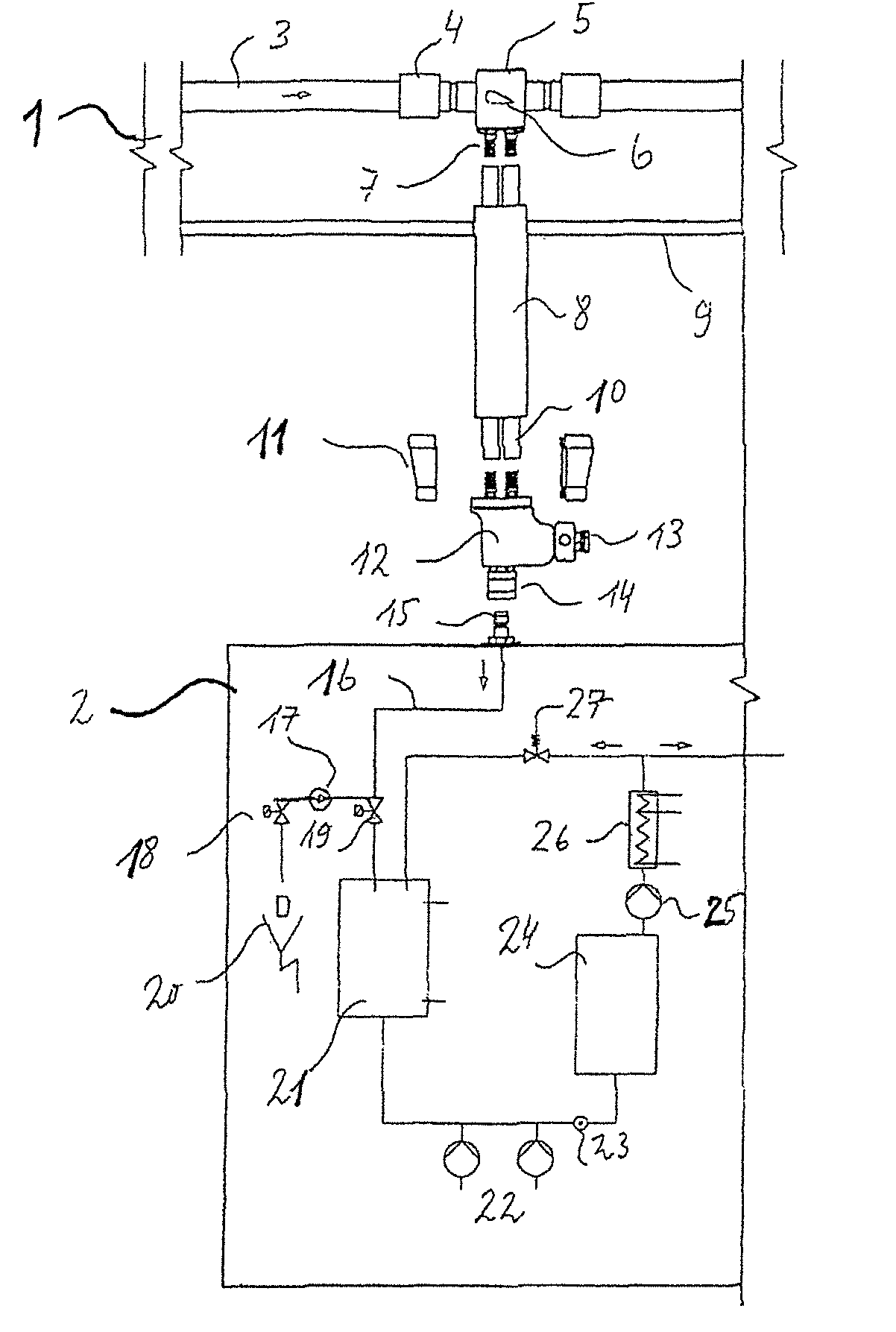
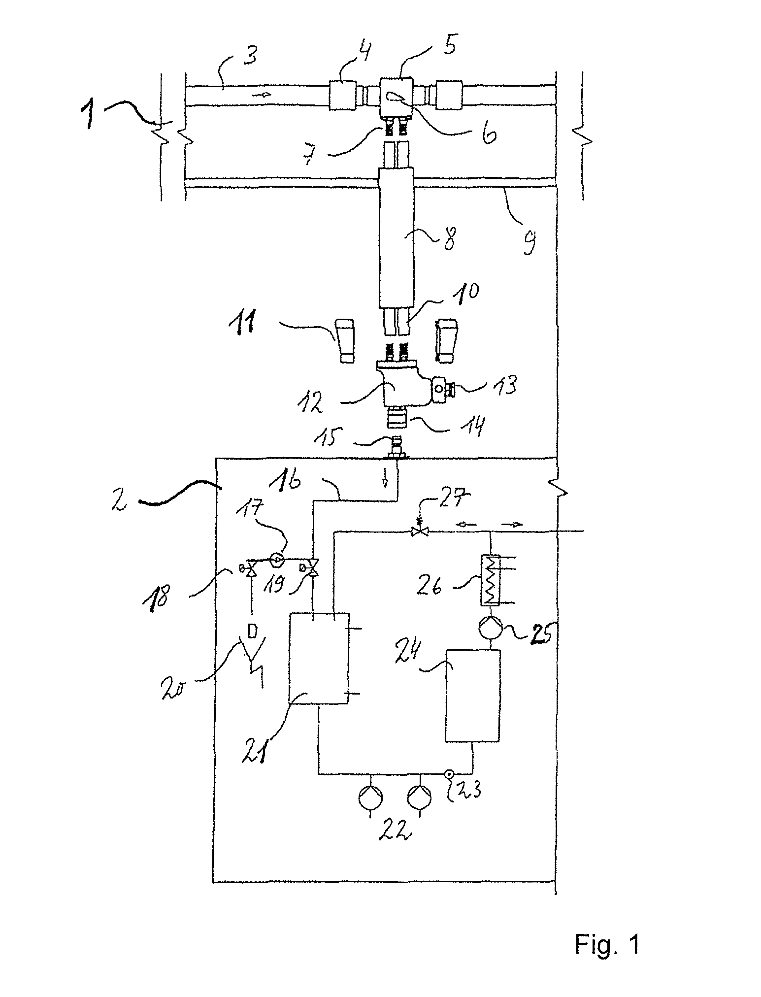
[0045]FIG. 1 shows the procedure of the invention. The part marked with 1 is the media supply; the part marked with 2 is the dialysis device. The permeate is passed through the conduit 3 to the ring-line connection block 5 (hereinafter called “RLB”). The ring line may here be connected by means of the press sleeve 14 or by a welding method. The interior of the RLB contains the flow body 6 which guides part of the permeate via the connections of the secondary ring line 7 and the inliner hoses 10 to the device connection block 12 (hereinafter called “GAB”). The strain relief shells 11 fix the insulating hoses 8 in the compressed state. In the opened state of the water inlet valve 19 a partial permeate stream is passed via the connection coupling 14 to the supply tank 21 of the dialysis device. During the flushing and cleaning cycle a def...


PUM

PropertyMeasurementUnit
areaaaaaaaaaaa
sizeaaaaaaaaaa
temperatureaaaaaaaaaa

Abstract

The fluid system for supplying a dialysis device with permeate has a secondary ring line which is guided within a common insulating hose or another form-fit sheathing. Thus, heat loss is reduced and use is facilitated. The insulating hose having the inner lines is adapted to a flow-optimized coupling handpiece having low dead space, which can preferably be coupled to a mating coupling piece.

Description

CROSS REFERENCE[0001]This application is a U.S. National Phase under 35 U.S.C. §371 of International Application No. PCT / DE2011 / 000167, filed Feb. 22, 2011, which claims priority from German Patent Application No. 10 2010 009 816.7, filed Mar. 2, 2010.FIELD OF THE INVENTION[0002]The present invention refers to a fluid system for supplying a device, particularly a dialysis device, with ultrapure liquid, particularly permeate, comprising a liquid-conducting conduit from which a secondary line, particularly a secondary ring line, branches off and ultrapure liquid is supplied through said secondary ring line to the device.[0003]This may be ultrapure liquid or a more or less ready-for-use dialysis liquid or a concentrate of said liquid that is used in the individual dialysis device by dilution with water and / or other constituents for preparing the dialysis liquid.[0004]Devices of such types are suited in dialysis devices particularly for the supply with the water needed for preparing the...

Claims


Application Information

Patent Timeline
Patent Type & Authority Patents(United States)
IPC IPC(8): F17D3/00
CPCF16L41/03A61M39/16A61M2205/84F16L37/40A61M39/105A61M39/26A61M1/1656Y10T137/87265
Inventor VOLKER, MANFRED
Owner VIVONIC GMBH
Why Eureka
Try Eureka