
Method and apparatus for removing residual biocide from a decontamination area

a biocide and decontamination area technology, applied in the direction of fire rescue, life-saving devices, disasters, etc., to achieve the effect of optimizing the efficiency of catalyst panels, optimizing gas flow rates, and improving the efficiency of aerators

Inactive Publication Date: 2014-07-29
NANOMIST SYST
View PDF4 Cites 1 Cited by
  • Summary
  • Abstract
  • Description
  • Claims
  • Application Information

AI Technical Summary

Benefits of technology

The present invention is about an apparatus and method for improving the efficiency of an aerator used for removing residual biocide. It includes an aerator assembly that controls the biocide-laden air flow and direction, and a high surface area catalyst panel. The catalyst panel efficiency is optimized by selection of the catalyst material and designing a catalyst bed with optimum porosity and substrate configuration. The apparatus further comprises an inlet and an outlet configured such that cleaned gas does not prematurely mix to cause undue dilution of the remaining biocide-laden gas in the room. The method involves maximizing the residence time of the contaminated gas within the catalyst panel by optimizing the air transport rates, the ratio of gas flow rate to the total catalyst active surface area ratio, momentum transfer, the residence time, the face velocity, and the effective catalyst area exposed to gas interaction including orientation. The flow pattern of gas through the device is configured such that the catalyst efficiency is maximized and the need for additional flow patterns within the device is unnecessary, and significantly improves the aeration rate.

Problems solved by technology

Further, the flow pattern of gas through the device is configured such that the catalyst efficiency is maximized and the need for additional flow patterns within the device is unnecessary, and significantly improves the aeration rate.

Method used


Image

  • Method and apparatus for removing residual biocide from a decontamination area
  • Method and apparatus for removing residual biocide from a decontamination area
  • Method and apparatus for removing residual biocide from a decontamination area

Examples


example 1

[0049]An aeration system having a twin aerator assembly, or a first aerator and an essentially identical second aerator, similar to the design shown in FIG. 1B, comprises a housing having an air intake plenum on the base side; the air moving devices are blowers, and two blowers are mounted within the housing, each blower having a volumetric flow of 1300 CFM; two air filters are mounted downstream of the air moving devices; two catalyst panels each comprising a ceramic honeycomb substrate with 400 cells per square inch washcoated with palladium to deliver a palladium concentration of 15 g / ft2 wherein each catalyst panel has dimensions of 6 inches (length)×6 inches (height)×2 inches (thickness); and two grids are mounted within the housing, one each providing protective cover for the catalyst panels. The blowers are controlled to push HP-laden air through the catalysts panels. For the first aerator, the average face velocity through the catalyst is about 5 m / s, the HP mass injected is...

example 2

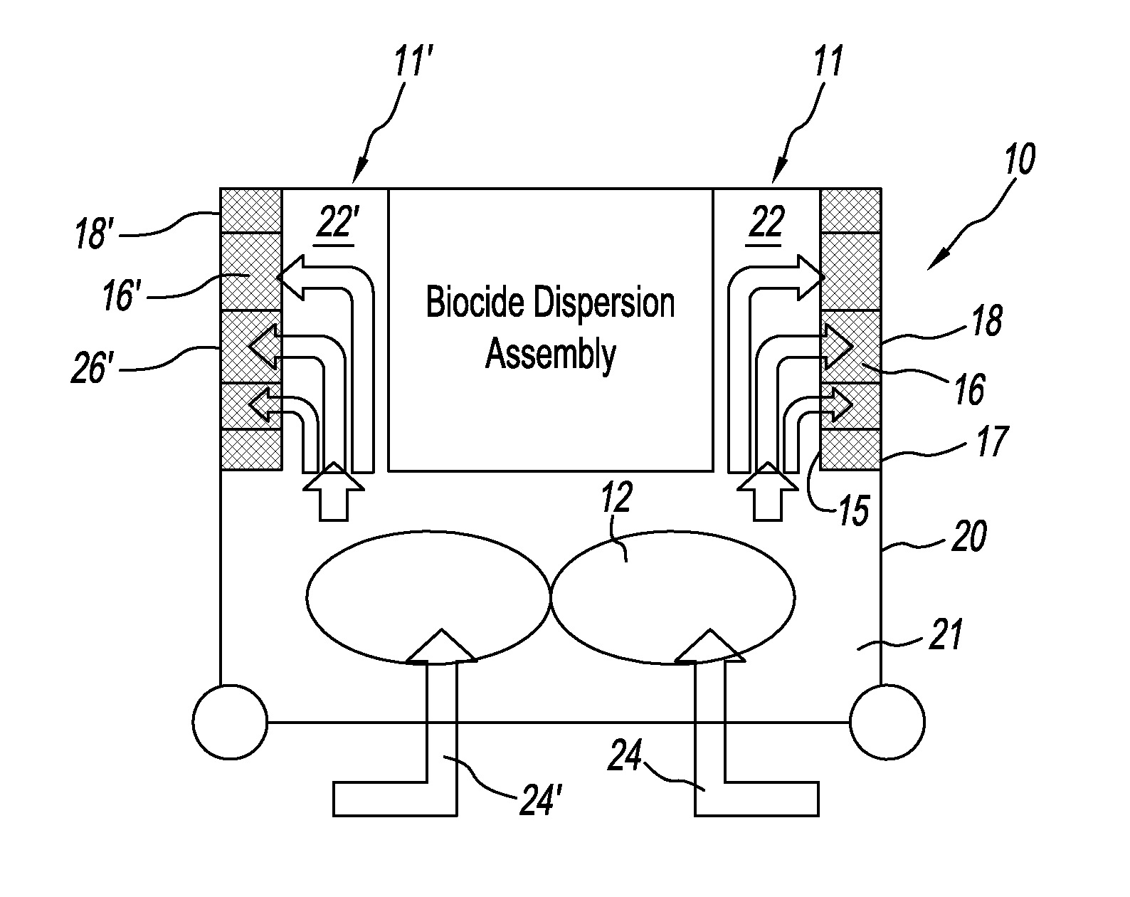
[0050]An aeration system having an annular airflow aerator assembly, similar to the device shown in FIG. 1A, comprises a housing having an air intake plenum on the base side; the air moving device is a motorized impeller fan and one fan is mounted within the housing, the fan having a volumetric flow of 4000 CFM; and, twenty-eight catalyst panels, each comprising a ceramic honeycomb substrate with 400 cells per square inch washcoated with palladium to deliver a palladium concentration of 15 g / ft2 wherein each catalyst panel has dimensions of 6 inches (length)×6 inches (height)×2 inches (thickness) for a total catalyst face area of 7 ft2. The fan is controlled to push air through the catalyst panels. The average face velocity through the catalyst is about 6 m / s, the biocide is 27% by weight hydrogen peroxide solution injected into an enclosed space having a volume of 36 m3 to deliver a mass of HP of about 25 g (this results in a mass concentration in the space of about 0.7 g / m3), the ...

example 3

[0051]Using the same system as in Example 2 except changing the 27% HP solution to a 35% HP solution, the aeration rate varied from 2.5-3.8 g / min.


PUM

PropertyMeasurementUnit
active surface areaaaaaaaaaaa
surface areaaaaaaaaaaa

Abstract

An apparatus and method are disclosed for improving the efficiency of an aerator which is used for removing residual biocide used for decontamination, sterilization, sanitation, or disinfection processes. The apparatus comprises an aerator assembly that produces an optimum air flow region and a high surface area catalyst panel. The method comprises utilizing the apparatus with optimizing gas flow rates, residence time of the contaminated gas within the catalyst panel, air flow pattern, air transport rate, cleaned air discharge pattern, and the nature and configuration of the catalyst.

Description

CROSS-REFERENCE TO PRIOR APPLICATIONS[0001]The present application does not claim priority to any previously filed U.S. patent applications.BACKGROUND[0002]The present invention relates to a system and a method for reducing residual biocide vapor following an area decontamination process to a level safe for reentry into the area. More specifically, this invention relates to a method and apparatus for rapidly reducing the hydrogen peroxide (HP) vapor concentration from a volume in an area decontamination process. Rapid removal of the residual HP minimizes the downtime of the facility thereby increasing productivity. The present inventive apparatus comprises an aerator having a high surface area catalyst panel. Rapid HP vapor concentration reduction is achieved by optimizing air flow pattern, air transport rate, cleaned air discharge pattern, and the nature and configuration of the catalyst. The result is a 3- to 4-fold efficiency increase as compared to the prior art.[0003]There is a...

Claims


Application Information

Patent Timeline
Patent Type & Authority Patents(United States)
IPC IPC(8): A61L9/00
CPCA61L9/00A61L2/00
Inventor ADIGA, KAYYANI C.ADIGA, RAJANIHATCHER, JR., ROBERT F.
Owner NANOMIST SYST
Learn More