Secondary-hardening gear steel

a gear steel and second-hardening technology, applied in the field of high-performance carburized gear steel, can solve the problems of diminishing durability improvement returns, rotorcraft industry has not adopted a new gear steel for over twenty years, etc., and achieves the effects of high surface hardness, maximum driving force of m2c, and high hardness

Active Publication Date: 2014-08-12
QUESTEK INNOVATIONS LLC
View PDF23 Cites 25 Cited by
  • Summary
  • Abstract
  • Description
  • Claims
  • Application Information

AI Technical Summary

Benefits of technology

[0005]Briefly, the present invention comprises a high-performance gear steel which is especially useful for rotorcraft transmissions. The steel exhibits an increase in surface hardness and core fracture toughness compared to conventional carburized gear steels. The steel is designed for a reasonable carbide solvus temperature, which, in turn, enables gas or vacuum carburization. Upon gas quenching from the solution heat treatment temperature, the steel transforms into a predominantly lath martensitic matrix. During tempering, an optimal strengthening dispersion of secondary M2C carbide precipitates, where M is Mo, Cr, W and / or V. The high tempering temperature of the steel enables higher operating temperatures in transmission components compared to conventional gear steels like X53 or 9310.
[0006]To achieve high core toughness, the matrix composition is carefully balanced to ensure the ductile-to-brittle transition is sufficiently below room temperature. The designed composition also effectively limits the thermodynamic driving force for precipitation of embrittling Topologically-Close-Packed (TCP) intermetallic phases such as σ and μ. Toughness of the invented steel is further enhanced by the distribution of a fine dispersion of grain-pinning particles that are stable during carburization and solution heat treatment cycles. The grain-pinning particles are MC carbides, where M=Ti, Nb, Zr, V with Ti preferred, that dissolve during homogenization and subsequently precipitate during forging.
[0008]The exemplary steel of the invention is designated as C64 in the above table. By virtue of inclusion of W, this steel is distinct from the steels disclosed in U.S. Pat. No. 6,464,801 (i.e. A1, C2, and C3). Inclusion of W increases the M2C driving force similar to Cr or Mo, and uniquely limits the thermodynamic driving force for precipitation of undesirable TCP phases. Whereas Mo and Cr preferentially promote σ-phase more than μ-phase, W provides a reverse effect. Thus, by adding W, the total driving force for σ- and μ-phases is balanced and precipitation of either TCP phase is avoided.
[0009]Alloy C69B is a counterexample. Although alloy C69B does include W and successfully tends to avoid the precipitation of TCP phases, insufficient Ni in the matrix places the ductile-to-brittle transition above room temperature. The Ni content is thus greater in alloys of the embodiment of the invention to place the ductile-to-brittle transition below room temperature and concurrently maximize the driving force for M2C, enabling the highest surface hardness at a usable toughness compared to any other known secondary-hardening steel.
[0010]Due to high surface hardness, good core toughness, and the high-temperature capability, the disclosed steel is considered especially utilitarian with respect to gears for helicopter transmissions. Other uses of the steel include vehicle gearing and armor. With respect to the constituents in the exemplary steel set forth above, the alloy preferably includes a variance in the constituents in the range of plus or minus five percent of the mean value.

Problems solved by technology

However, the rotorcraft industry has not adopted a new gear steel for over twenty years, and instead focused on surface processing optimizations such as laser-peening, super-finishing, and directional forging.
Such processes are providing diminishing returns in durability improvements.

Method used


Image

  • Secondary-hardening gear steel
  • Secondary-hardening gear steel
  • Secondary-hardening gear steel

Examples


example 1

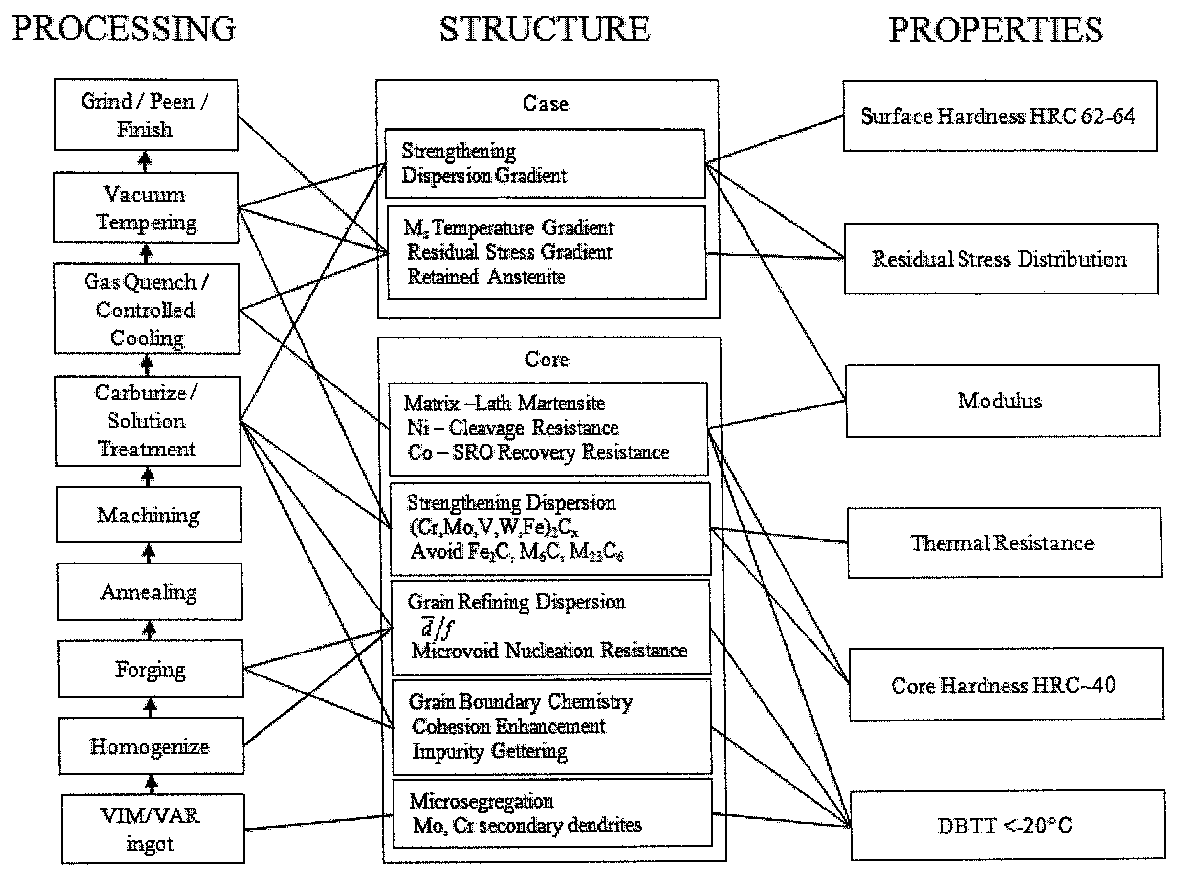
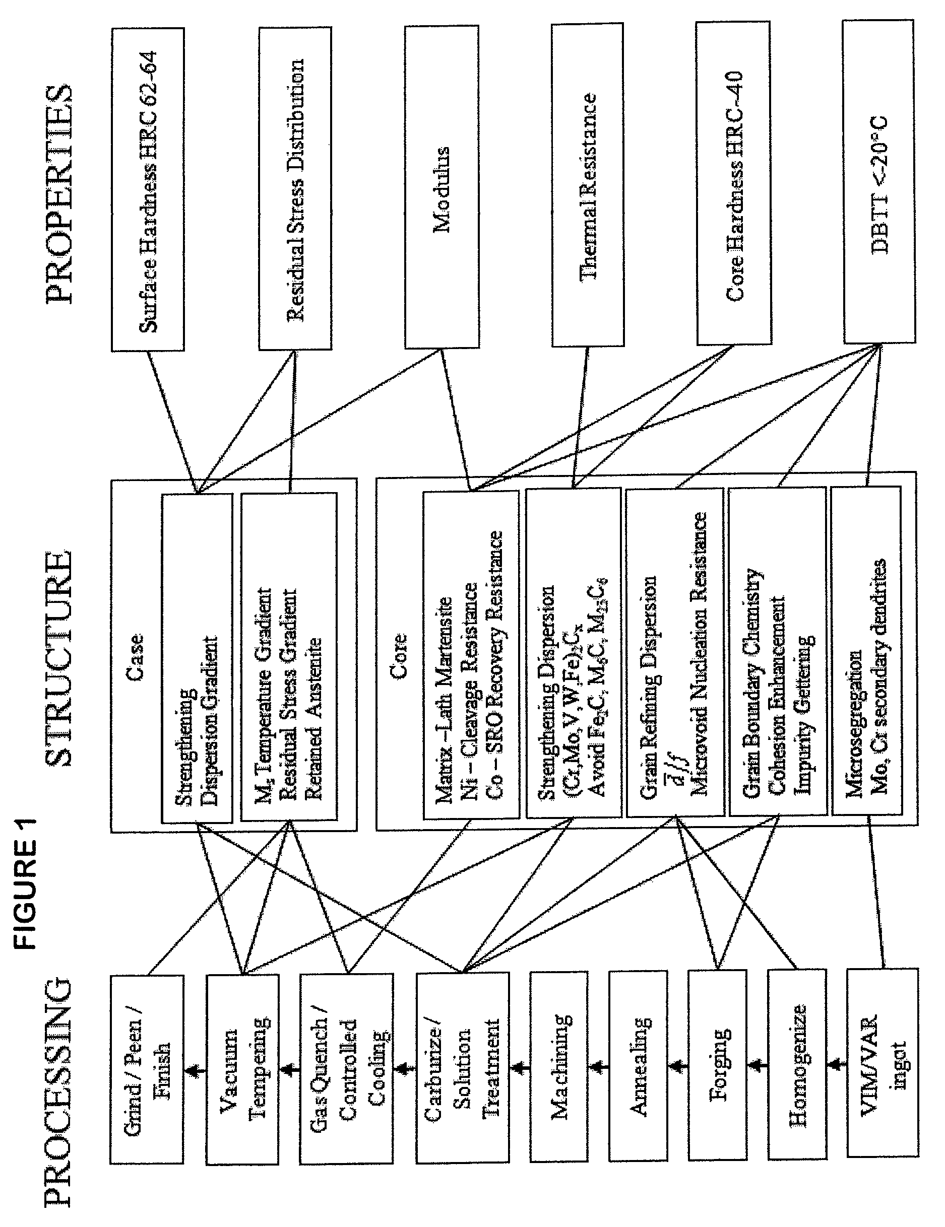
[0024]A 3,000-lb vacuum induction melt of Fe-16.1Co-4.5Cr-4.3Ni-1.8Mo-0.12C-0.1V-0.1W-0.02Ti (wt %) was prepared from high purity materials. The melt was converted to a 1.5-inch-square bar. The optimum processing condition was to solutionize at 1050° 90 minutes, quench with oil, immerse in liquid nitrogen for 1 hour, warm in air to room temperature, temper at 468° C. for 56 hours, and cool in air. The DBTT in this condition was between 150° C. and 250° C.

example 2

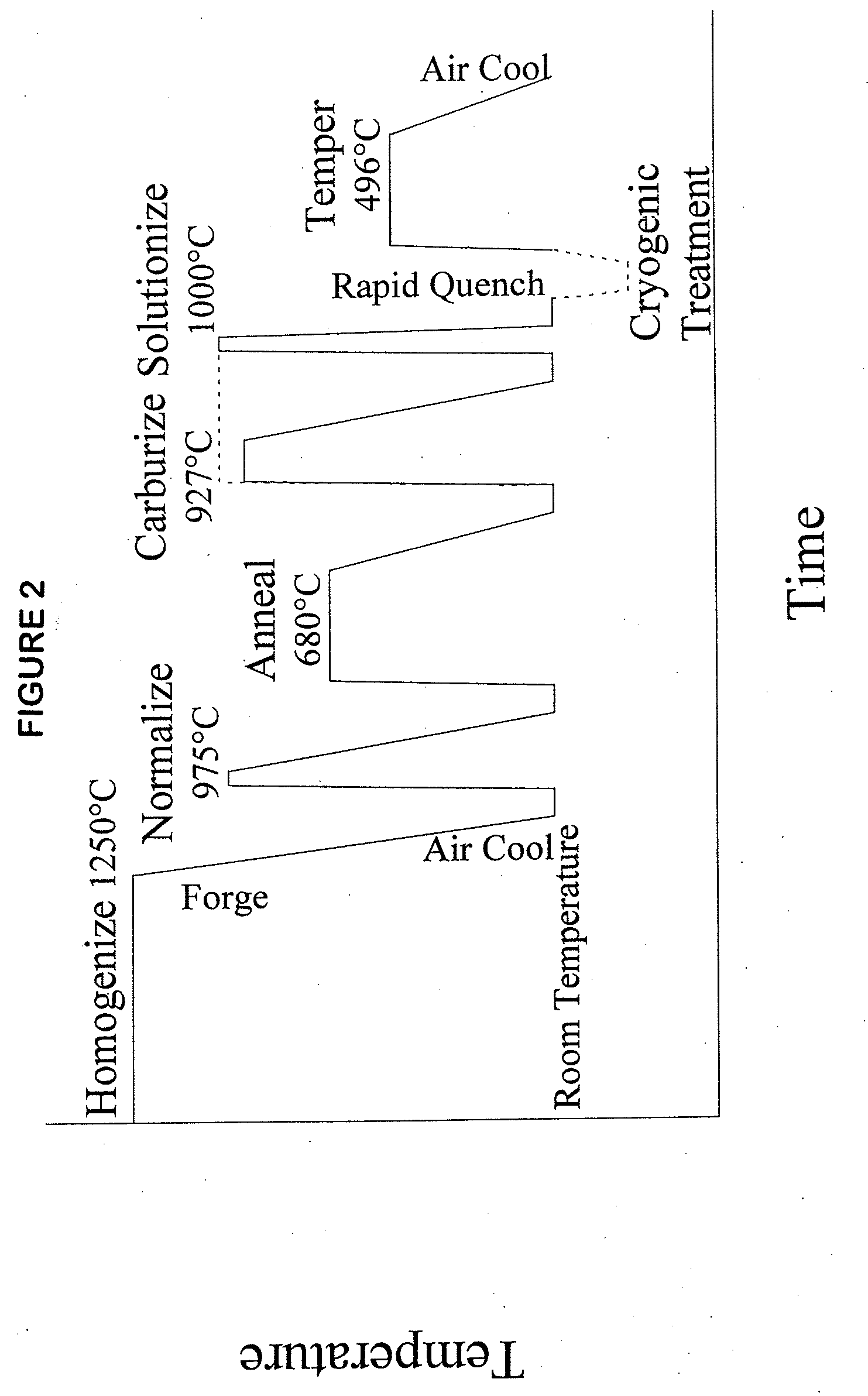
[0025]A 30-lb vacuum induction melt of Fe-17.0Co-7.0Ni-3.5Cr-1.5Mo-0.2W-0.12C-0.03Ti (wt %) was prepared from high purity materials. Ms of the case material was measured as 162° C. from dilatometry, in agreement with model predictions. The carburization response of this prototype was determined from hardness measurements. The optimum processing condition was to carburize and concurrently solutionize the steel at 927° C. for 1 hour, quench with oil, and immerse in liquid nitrogen. A subsequent tempering at 482° C. for 16 hours resulted in a surface-hardness of 62.5 HRC. The case depth of the carburized sample was about 1 mm. An atom-probe tomography analysis of the steel verified the absence of TCP phases.

example 3

[0026]A 300-lb vacuum induction melt of Fe-17.0Co-7.0Ni-3.5Cr-1.5Mo-0.2W-0.12C (wt %) was prepared from high purity materials. Because this prototype did not include Ti, the grain-pinning dispersion of TiC particles could not form. As a result, the average grain diameter was 83μ and toughness was very low. The CVN impact energy of the core material from this prototype was 5 ft-lb at an Ultimate Tensile Strength (UTS) of 238 ksi.


PUM

PropertyMeasurementUnit
thicknessaaaaaaaaaa
ductile-to-brittle transition temperatureaaaaaaaaaa
core toughnessaaaaaaaaaa

Abstract

A case hardened gear steel having enhanced core fracture toughness includes by weight percent about 16.3Co, 7.5Ni, 3.5Cr, 1.75Mo, 0.2W, 0.11C, 0.03Ti, and 0.02V and the balance Fe, characterized as a predominantly lath martensitic microstructure essentially free of topologically close-packed (TCP) phases and carburized to include fine M2C carbides to provide a case hardness of at least about 62 HRC and a core toughness of at least about 50 ksi√in.

Description

CROSS REFERENCE TO RELATED APPLICATION[0001]This is a utility application based upon the following provisional application which is incorporated herewith by reference and for which priority is claimed: U.S. Ser. No. 60 / 957,307 filed Aug. 22, 2007.GOVERNMENT INTERESTS[0002]Activities relating to the development of the subject matter of this invention were funded at least in part by United States Government, Naval Air Warfare Center Contract No. N68335-06-C-0339, and thus may be subject to license rights and other rights in the United States.BACKGROUND OF THE INVENTION[0003]In a principal aspect, the present invention relates to a high-performance carburized gear steel that can improve the performance of rotorcraft power transmissions, due to a unique and useful combination of surface hardness and core toughness. The U.S. Navy estimates that a 20% increase in gear durability would provide an annual cost saving of $17 million to the Defense Logistics Agency. However, the rotorcraft ind...

Claims


Application Information

Patent Timeline
Patent Type & Authority Patents(United States)
IPC IPC(8): C23C8/22C21D1/22C21D1/25C21D6/00C21D6/02C21D6/04C21D9/32C22C5/02C22C38/00C22C38/08C22C38/12C22C38/14C22C38/18C22C38/22C22C38/30C22C38/40C22C38/44C22C38/46C22C38/50C22C38/52C23C8/20C23C8/32
CPCC22C38/44C21D1/22C21D6/004C21D6/007C22C38/52C21D6/02C21D6/04C21D9/32C21D2211/008C21D1/25
Inventor WRIGHT, JAMES A.SEBASTIAN, JASON
Owner QUESTEK INNOVATIONS LLC
Why Eureka
Try Eureka