Switching coordination of distributed dc-dc converters for highly efficient photovoltaic power plants

a technology of photovoltaic power plants and converters, applied in the direction of electric variable regulation, process and machine control, instruments, etc., can solve the problems of large input power, sharp drop in light load efficiency of these converters, and still suffer, so as to increase the energy yield of the pv power plant

Active Publication Date: 2014-09-09
GENERAL ELECTRIC CO
View PDF12 Cites 7 Cited by
  • Summary
  • Abstract
  • Description
  • Claims
  • Application Information

AI Technical Summary

Benefits of technology

[0009]at least one string of PV modules, wherein each dc-dc converter receives power from at least one corresponding string of PV modules, and further wherein at least one dc-dc converter is configured to transfer power to a common dc-bus based upon the total system power available from each of its corresponding strings of PV modules such that each dc-dc converter transferring power to the common dc-bus continues to operate within its optimal efficiency range to increase the energy yield of the PV power plant.
[0012]transferring power to a common dc-bus from at least one of the one or more dc-dc converters such that the power transferred from each dc-dc converter contributing power to the common dc-bus is based upon the total system power available from each of its corresponding strings of PV modules, and further such that each dc-dc converter transferring power to the common dc-bus continues to operate within its optimal efficiency range to increase the energy yield of the PV power plant.
[0013]According to yet another embodiment, a string level maximum power point distributed photovoltaic (PV) power plant comprises a plurality of distributed dc-dc converters configured to switch in coordination with one another such that at least one dc-dc converter transfers power to a common dc-bus based upon the total system power available from one or more corresponding strings of PV modules, and further such that each dc-dc converter transferring power to the common dc-bus continues to operate within its optimal efficiency range to increase the energy yield of the PV power plant.

Problems solved by technology

Converter losses however, constitute a larger percentage of the input power as this power level becomes smaller and consequently, light load efficiency of these converters fall sharply.
Although distributed PV plant architectures provide increased energy yield and operational flexibility, they still suffer from reduced power conversion efficiency at partial and / or light loading in PV power plants.

Method used


Image

  • Switching coordination of distributed dc-dc converters for highly efficient photovoltaic power plants
  • Switching coordination of distributed dc-dc converters for highly efficient photovoltaic power plants
  • Switching coordination of distributed dc-dc converters for highly efficient photovoltaic power plants

Examples


Embodiment Construction

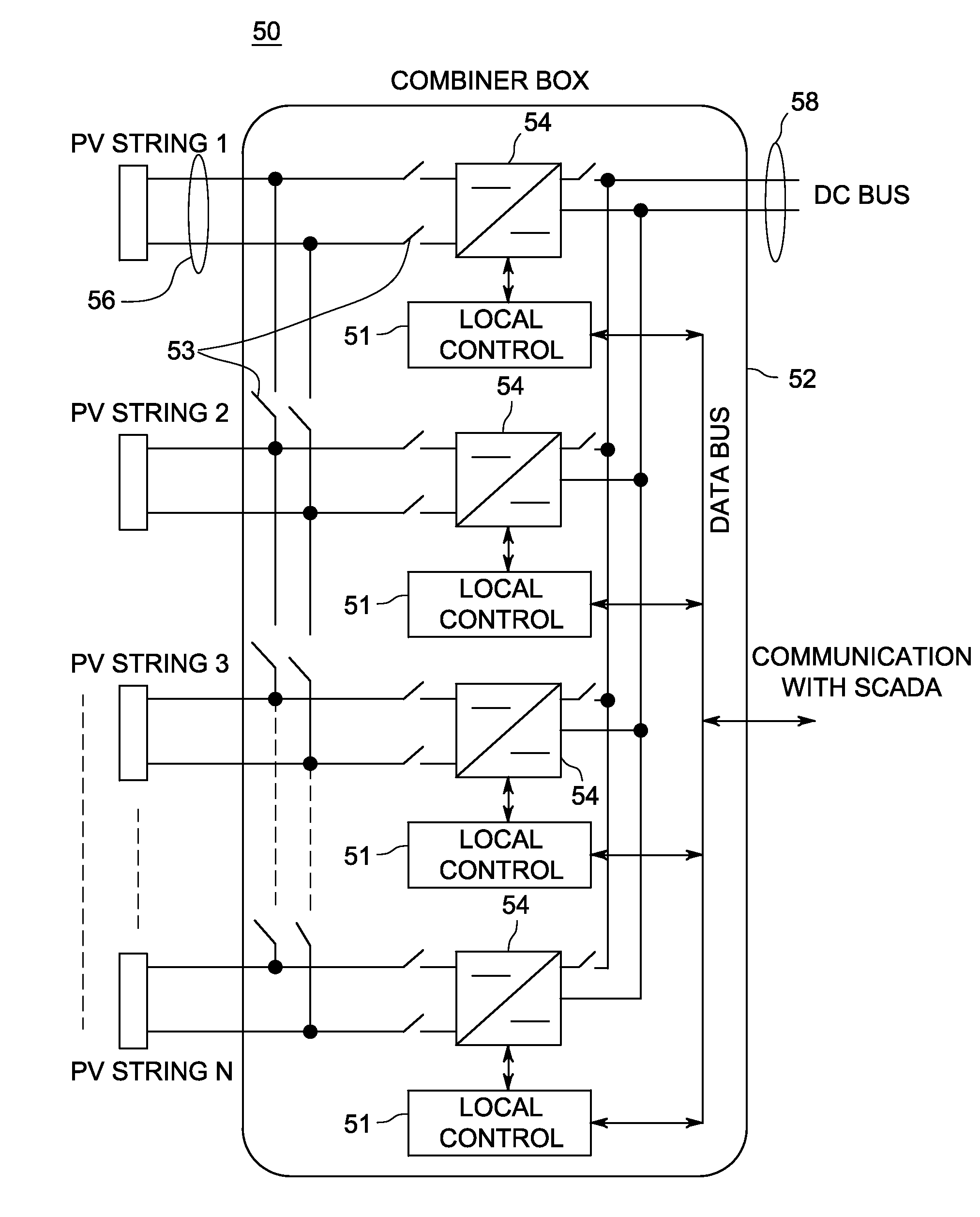
[0029]The embodiments described herein provide increased power conversion efficiency of a solar plant by selectively operating a number of dc-dc converters that is sufficient to handle the power generated by the PV modules while operating in their highest efficiency operating region since each converter will see a higher input power to process than when all converters are operated all the time. Consequently, the individual operational converter efficiency will remain higher for a wider range of total input power.

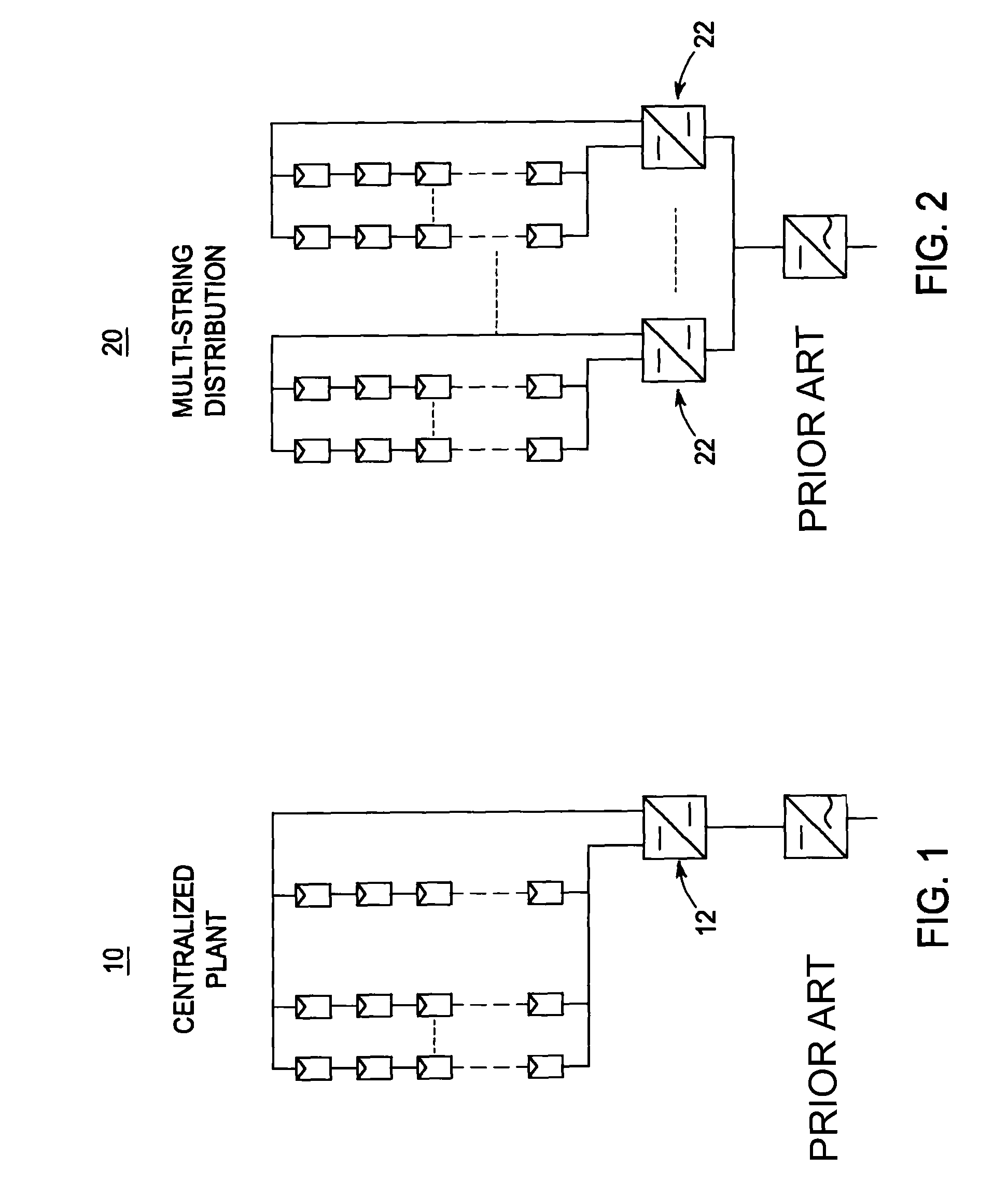
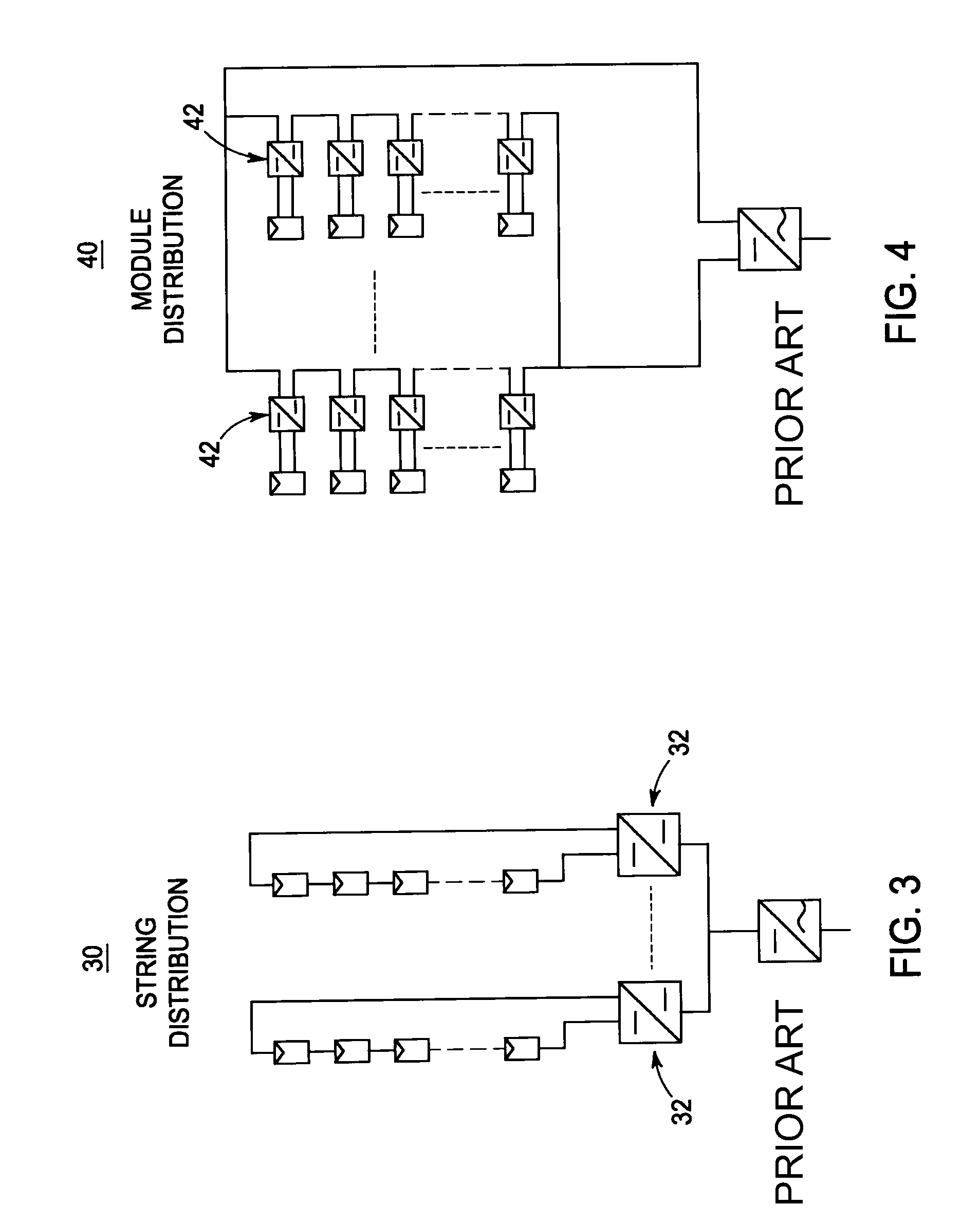
[0030]PV plant architectures take several forms starting from the conventional central inverter system to a fully distributed system such as described herein with reference to FIGS. 1-4. All of the PV plant architectures depicted in FIGS. 2-4 can be considered to have multiple dc-dc converters. Selective operation of converters becomes inapplicable in the case of module level distribution such as illustrated in FIG. 4 because it may result in the total shutdown of an associa...


PUM


Abstract

A distributed photovoltaic (PV) power plant includes a plurality of distributed dc-dc converters. The dc-dc converters are configured to switch in coordination with one another such that at least one dc-dc converter transfers power to a common dc-bus based upon the total system power available from one or more corresponding strings of PV modules. Due to the coordinated switching of the dc-dc converters, each dc-dc converter transferring power to the common dc-bus continues to operate within its optimal efficiency range as well as to optimize the maximum power point tracking in order to increase the energy yield of the PV power plant.

Description

STATEMENT REGARDING FEDERALLY SPONSORED RESEARCH & DEVELOPMENT[0001]This invention was made with U.S. Department of Energy support under contract number DE-EE0000572. The Government has certain rights in the invention.BACKGROUND[0002]This invention relates generally to photovoltaic (PV) power plants, and more particularly, to a system and method for coordinating the switching of distributed dc-dc converters associated with PV modules to yield highly efficient photovoltaic power plants.[0003]PV plant architectures take several forms starting from the conventional central inverter system to a fully distributed system as shown in FIGS. 1-4, all of which can be considered to have multiple dc-dc power converters. FIG. 1, for example, illustrates a PV plant architecture 10 that employs a two-stage central inverter 12. FIG. 2 illustrates a PV plant architecture 20 that employs a string combiner distribution of dc-dc converters 22. FIG. 3 illustrates a PV plant architecture 30 that employs ...

Claims


Application Information

Patent Timeline
Patent Type & Authority Patents(United States)
IPC IPC(8): H02J1/12H02M3/00H02J3/38H02M1/00H02M3/158
CPCH02J3/385H02M3/1584H02M2001/0067Y02B70/16Y02E10/58H02M2001/0032Y10T307/653H02J2300/26H02J3/381Y02B70/10Y02E10/56H02M1/0067H02M1/0032H02M1/0093H02J3/46
Inventor AGAMY, MOHAMMEDELASSER, AHMEDSABATE, JUAN ANTONIOGALBRAITH, ANTHONY WILLIAMHARFMAN TODOROVIC, MAJA
Owner GENERAL ELECTRIC CO
Why Eureka
Try Eureka