Method and device for generating optical signals

a technology of optical signals and optical signals, applied in the field of communication, can solve the problems of large volume high cost, complex structure, etc., and achieve the effects of reducing the requirements for input optical, reducing the cost of the device for generating optical signals, and reducing the loss of insertion caused by the clock modulator

Active Publication Date: 2014-09-09
HUAWEI TECH CO LTD
View PDF13 Cites 85 Cited by
  • Summary
  • Abstract
  • Description
  • Claims
  • Application Information

AI Technical Summary

Benefits of technology

[0008]In order to simplify the structure of the device for generating optical signals, reduce the costs and the insertion loss of the entire device, lower the requirements for input optical power and reduce the complexity of loop circuit control, the present invention is directed to a method and device for generating optical signals. The technical solution is as follows.
[0016]The technical solution of the present invention has the following beneficial effects.
[0017]RZ processing is performed on the NRZ data signals to generate a pair of complementary RZ data signal pairs, and the two RZ data signal pairs are modulated on light to generate an RZ-DQPSK optical signal without adding a clock modulator to cut the pulse of the NRZ-DQPSK signal to generate the RZ-DQPSK optical signal, so that the structural complexity and the cost of the device for generating optical signals are reduced, and at the same time, the insertion loss caused by the clock modulator is reduced, and the requirements for input optical power are lowered. Since no clock modulator is added in the present invention, the control of the bias point of the clock modulator is not required, so that the complexity of control caused by the clock modulator is reduced. Meanwhile, since no clock synchronization control caused by the clock modulator is involved, the complexity of synchronization control is reduced.

Problems solved by technology

In the prior art, the two stages of modulators are used to generate the RZ-DQPSK optical signal, which results in complex structure, high costs, and large volume of the device for generating optical signals.
The clock modulator needs to control a bias point, which increases the complexity of loop circuit control.
In addition, the phase of the clock must be synchronous with that of the data signal, but the synchronization control method is complex.

Method used


Image

  • Method and device for generating optical signals
  • Method and device for generating optical signals
  • Method and device for generating optical signals

Examples


embodiment 1

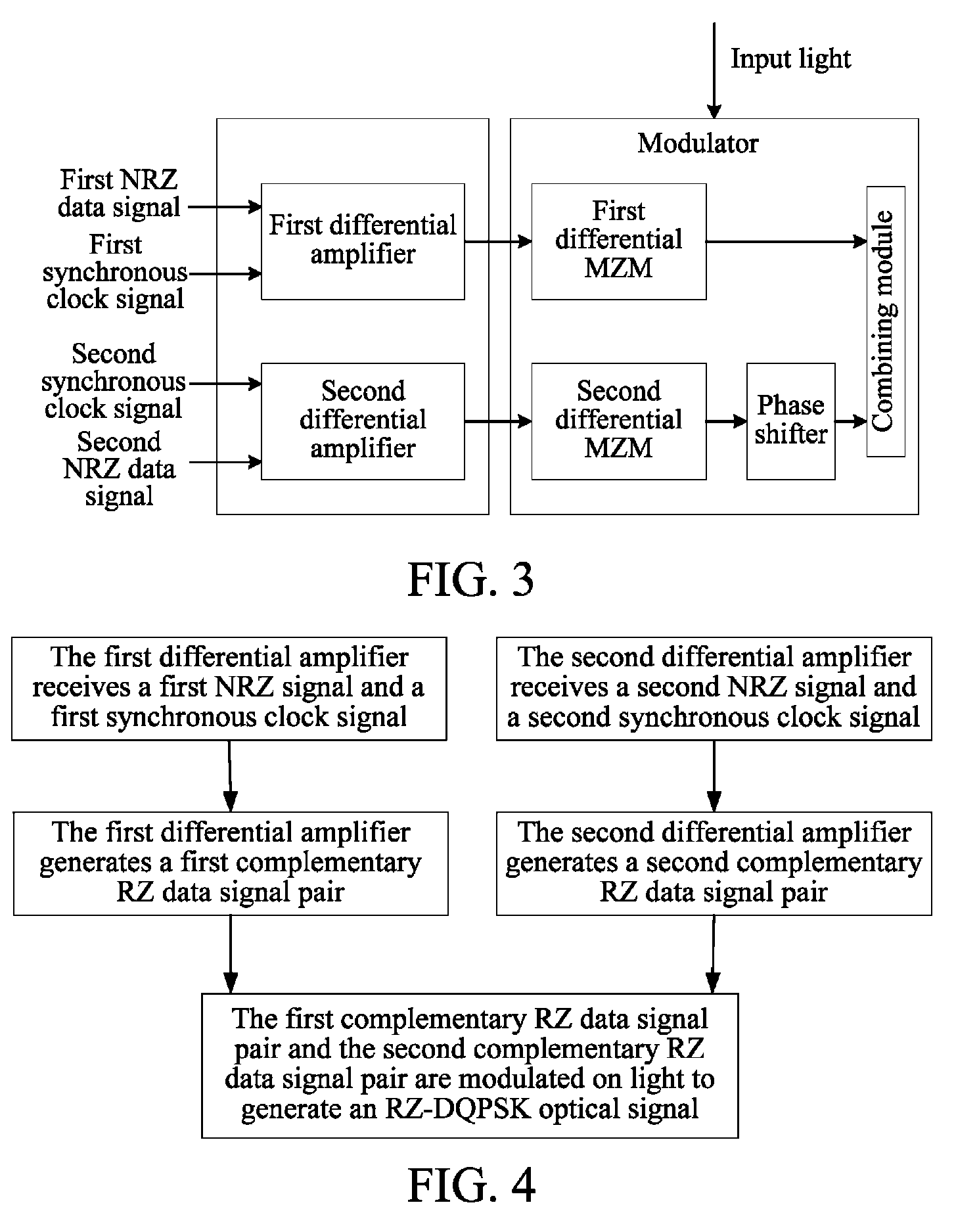
[0027]In this embodiment, two differential amplifiers respectively receive an NRZ data signal and a synchronous clock signal, and perform RZ processing on the two NRZ data signals to generate two RZ data signal pairs, where each pair of RZ data signals contain two complementary RZ data signals. At the same time, the two RZ data signal pairs are loaded onto a modulator to modulate light input into the modulator, so as to generate an RZ-DQPSK optical signal.

[0028]It should be noted that, although in this embodiment, two differential amplifiers are used to respectively receive an NRZ data signal and a synchronous clock signal and perform RZ processing on the two NRZ data signals, other manners may also be adopted, for example, two logic circuit units (for example, a combination of an AND gate and an OR gate) are used to respectively perform RZ processing on the two NRZ data signals, or an integrated differential amplifier or a logic circuit is used to load a synchronous clock signal fo...

embodiment 2

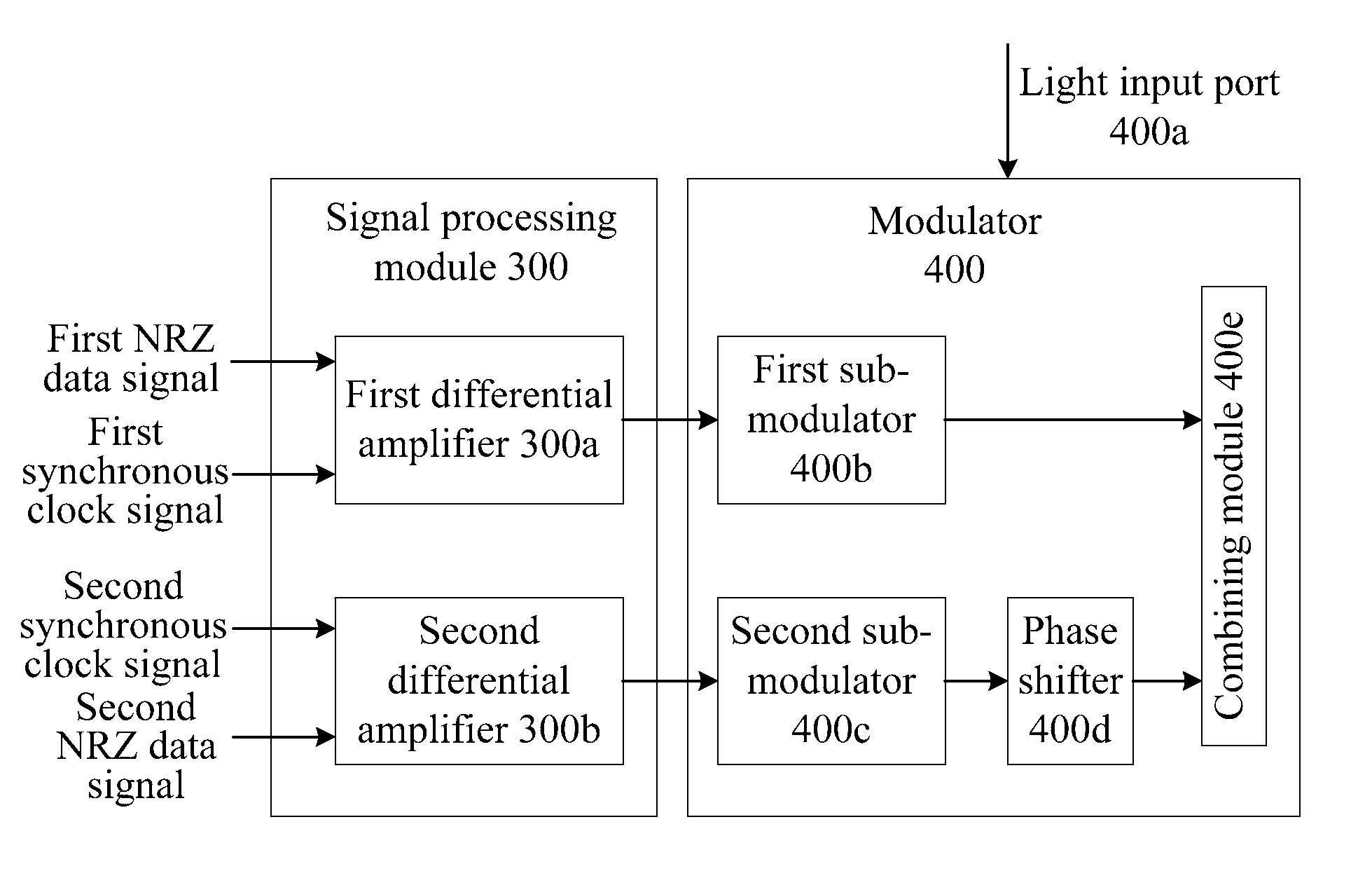
[0046]FIG. 7 shows a device for generating optical signals according to a second embodiment of the present invention. As shown in FIG. 7, the device includes a signal processing module 300 and a modulator 400.

[0047]The signal processing module 300 is configured to receive a first NRZ data signal and a synchronous clock signal, perform RZ processing to generate a first complementary RZ data signal pair, and output the first complementary RZ data signal pair; and receive a second NRZ data signal and a synchronous clock signal, perform RZ processing to generate a second complementary RZ data signal pair, and output the second complementary RZ data signal pair.

[0048]The modulator 400 is configured to receive input light, the first complementary RZ data signal pair, and the second complementary RZ data signal pair, and modulate the first complementary RZ data signal pair and the second complementary RZ data signal pair on the light to generate an RZ-DQPSK optical signal.

[0049]The signal ...

embodiment 3

[0065]In this embodiment, a device for generating optical signals is provided. The difference between this embodiment and the previous embodiment lies in that the signal processing module is an integrated differential amplifier, and the integrated differential amplifier receives a first NRZ data signal, a second NRZ data signal, and a synchronous clock signal simultaneously, where the three signals are synchronous (that is, the three signals have the same frequency and the same initial phase). It should be noted that, the synchronization of the three signals may be implemented by performing CDR through an existing PLL circuit. The three signals pass through the integrated differential amplifier, and according to the differential principle in the integrated differential amplifier, a first complementary RZ data signal pair and a second complementary RZ data signal pair are generated simultaneously, that is, one integrated differential amplifier achieves the functions of two differenti...


PUM


Abstract

The method includes: receiving a first Non Return to Zero (NRZ) data signal and a synchronous clock signal, and performing Return to Zero (RZ) processing to generate a first complementary RZ data signal pair; receiving a second NRZ data signal and a synchronous clock signal, and performing RZ processing to generate a second complementary RZ data signal pair; and modulating the first complementary RZ data signal pair and the second complementary RZ data signal pair on light to generate an RZ-Differential Quadrature Phase Shift Keying (RZ-DQPSK) optical signal. Through the method and device, RZ processing are performed on the NRZ data signals to generate the complementary RZ data signal pairs, and the complementary RZ data signal pairs are modulated on the light, thereby reducing the cost and the insertion loss of the entire device, lowering the requirements for input optical power and reducing the complexity of loop circuit control.

Description

CROSS-REFERENCE TO RELATED APPLICATIONS[0001]This application is a continuation of International Application No. PCT / CN2009 / 071267, filed on Apr. 15, 2009, which claims priority to Chinese Patent Application No. 200810128734.2, filed on Jun. 20, 2008, both of which are hereby incorporated by reference in their entireties.FIELD OF THE TECHNOLOGY[0002]The present invention relates to the field of communications, and more particularly to a method and device for generating optical signals.BACKGROUND OF THE INVENTION[0003]With the increasing demand for optical network capacity, the service transmission rate is developing from 10 Gb / s rate of current networks to 40 Gb / s and even 100 Gb / s. In high-speed optical transmission systems, selection of an optical modulation format is critical in the whole system. The optical modulation format is directly correlated to the properties of the optical transmission system such as transmission performance, spectral efficiency, nonlinear tolerance, and ...

Claims


Application Information

Patent Timeline
Patent Type & Authority Patents(United States)
IPC IPC(8): H04B10/00H04B10/50H04B10/516H04B10/556
CPCH04B10/5561H04B10/5051H04B10/5162H04B10/5053H04B2210/517
Inventor YU, DEZHONGQI, MING
Owner HUAWEI TECH CO LTD
Why Eureka
Try Eureka