
System and method for analyzing spiral resonators

a spiral resonator and spiral resonator technology, applied in the field of systems and methods for analyzing spiral resonators, can solve the problems of insufficient models for some applications, methods not necessarily producing the same, and inability to accurately predict the effect of the spiral resonator,

Inactive Publication Date: 2014-09-09
MITSUBISHI ELECTRIC RES LAB INC
View PDF6 Cites 5 Cited by
  • Summary
  • Abstract
  • Description
  • Claims
  • Application Information

AI Technical Summary

Benefits of technology

The patent text discusses the problem of accurately modeling the behavior of a circuit using a set of loops. The text explains that the way in which these loops are connected to each other is important, but it can be difficult to accurately calculate this connection. To solve this problem, the patent describes a method that takes into account the presence of ferromagnetic material inside the loops and approximates the shape of the loops using a simpler geometry. This method improves the accuracy of the circuit model without increasing the complexity of the analysis. Overall, the patent offers a solution for accurately simulating the performance of a circuit using a set of loops.

Problems solved by technology

These methods do not necessarily produce the same result.
However, those models are insufficient for some applications.
The inadequacies of the models can be due either to their inaccuracy or their excessive computational time, memory requirement, and cost.
Unfortunately, those methods require excessive computational time and memory.
Although circuit models can model spiral resonators, those models can be inaccurate.
Additionally or alternatively, the circuit model may be accurate for a specific geometry of spiral resonators, but be inaccurate or even inapplicable to another spiral resonator with a slight change in the geometry.
This inaccuracy is not surprising since the conventional models tend to oversimplify the complexity of the system.
This assumption is incorrect, and such model is not always optimal.

Method used


Image

  • System and method for analyzing spiral resonators
  • System and method for analyzing spiral resonators
  • System and method for analyzing spiral resonators

Examples


Embodiment Construction

[0055]The embodiments of the invention provide a method for analyzing a spiral resonator.

[0056]Problem Formulation

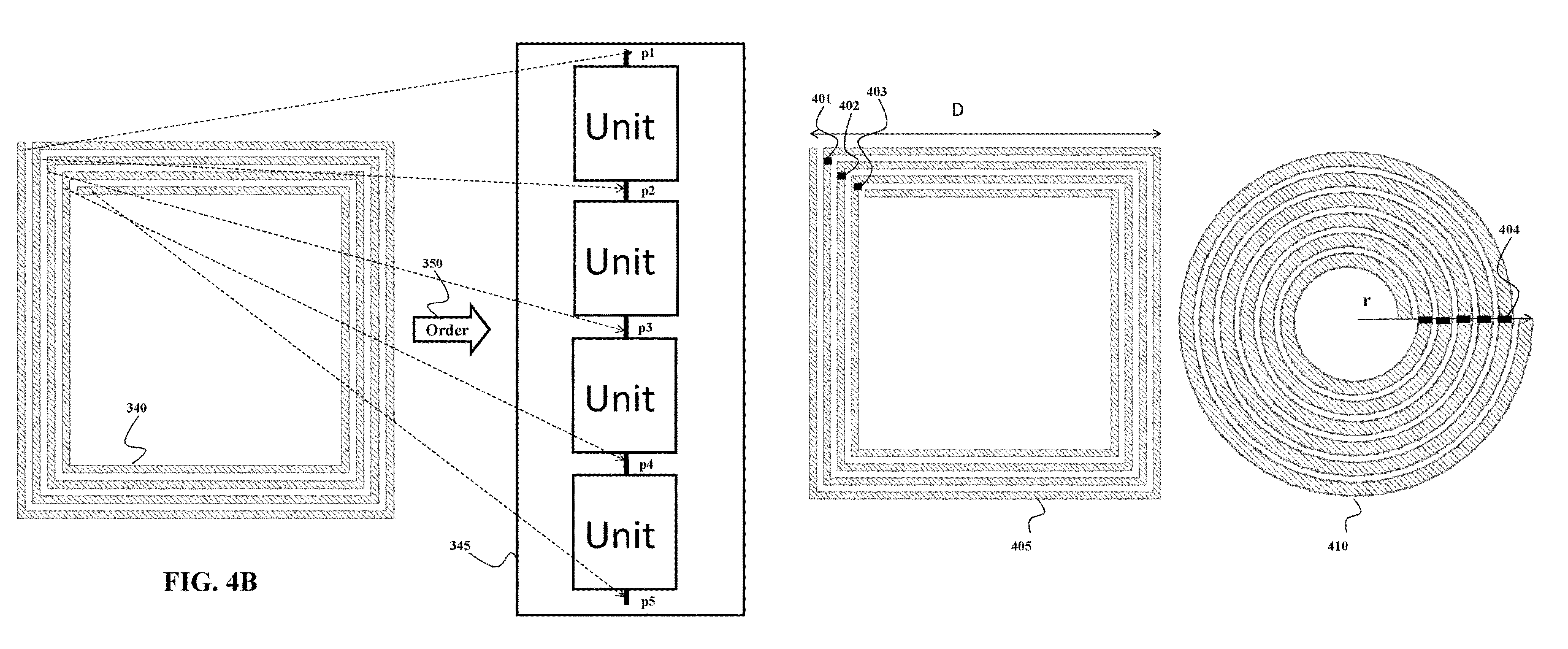
[0057]A tank circuit model for analyzing a spiral resonator assumes a uniform current density throughout the length of the spiral(s). This assumption is incorrect, because the current density distribution resembles a standing wave in which the nodes of the standing wave are located at the open leads of the spiral resonator.

[0058]Another problem with the tank circuit model is that the model cannot be used to gain insight into the electromagnetic properties of each loop of the spiral resonator and the interaction between the loops. The tank circuit model is like a black box in which the geometric properties of the spiral resonator are the inputs and only the resonant frequency of the spiral resonator is the output. An additional flaw in the tank circuit model of a spiral resonator is that it implicitly implies that a spiral resonator only has a single resonant frequency. H...


PUM


Abstract

A spiral resonator is analyzed by modeling a set of loops of the spiral resonator with a model of a circuit including a set of units, wherein each unit includes a resistor and an inductor to model one loop of the spiral resonator. Values of the resistor and the inductor of each unit are based on properties of a corresponding loop. Electrical connection of the loops is modeled by electrically connecting the units in a corresponding order of the loops. A capacitive coupling in the spiral resonator is modeled by connecting adjacent units with at least one capacitor having a value based on the capacitive coupling between two corresponding adjacent loops. An inductive coupling in the spiral resonator is modeled based on inductive coupling between pairs of loops. The operation of the spiral resonator is simulated with the model of the circuit.

Description

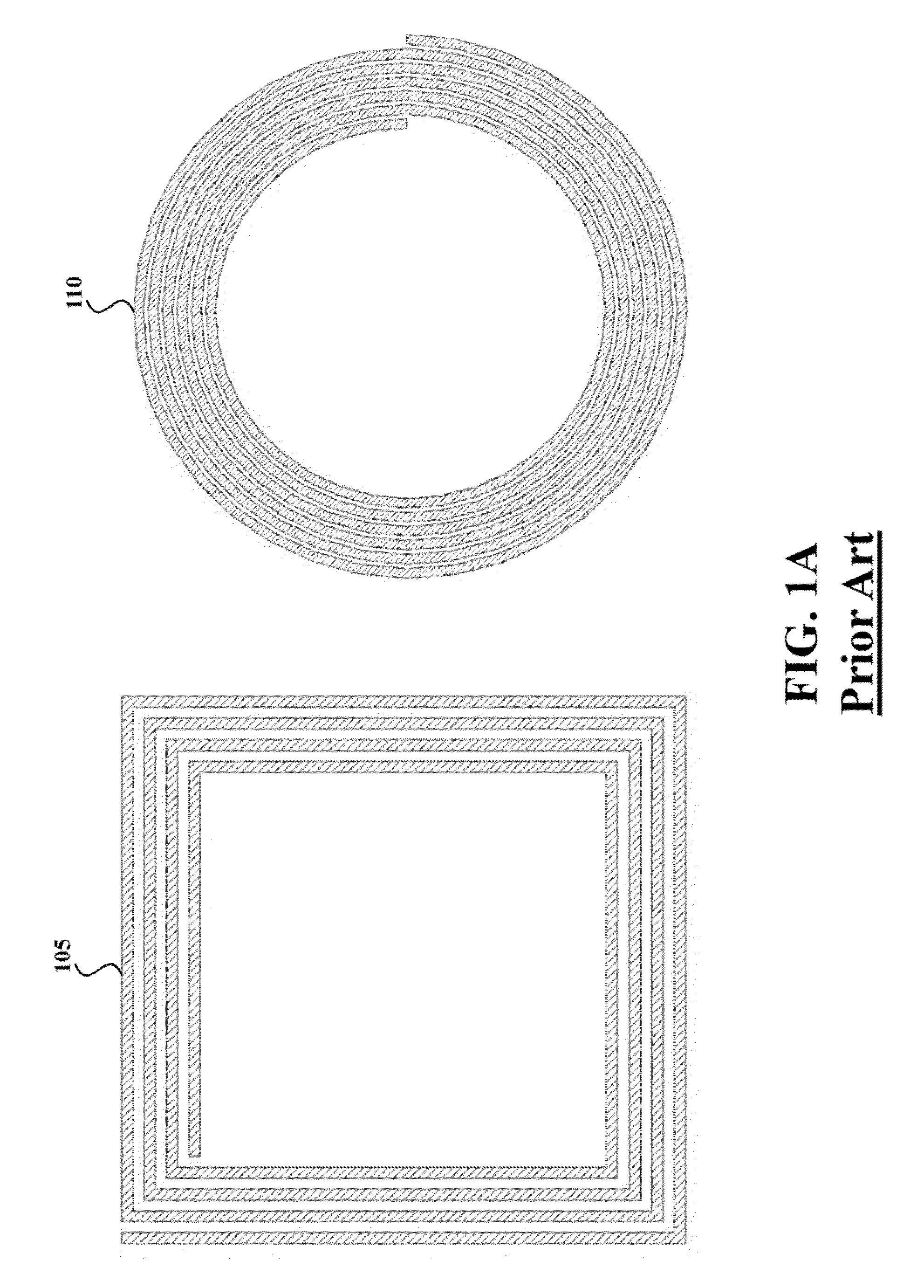
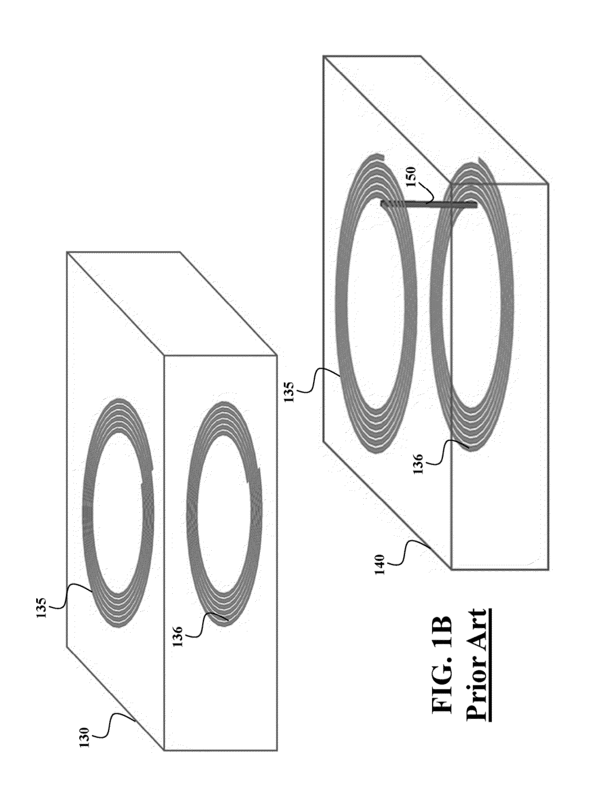
RELATED APPLICATION[0001]This Application claims priority to U.S. Provisional Patent entitled, “Method for Modeling Spiral Resonators” Application No. 61 / 565,711, filed on Dec. 1, 2011. The provisional application is incorporated herein by reference.FIELD OF THE INVENTION[0002]This invention relates generally to systems and methods for analyzing spiral resonators, and more particularly to modeling and analyzing the spiral resonators based on circuit topologies.BACKGROUND OF THE INVENTIONSpiral Resonators[0003]Spiral resonators have a conductive material (wire(s)) with a spiral structure designed to resonate at one or multiple frequencies. The value of spiral resonators can be shown through their application to both a single layer spiral and a double layer spiral resonators. FIG. 1A shows an example of two common single layer spiral structures, i.e., a square spiral 105 and an Archimedes spiral 110. All the wires of the single layer spiral are arranged in the same plane.[0004]FIG. 1B...

Claims


Application Information

Patent Timeline
Patent Type & Authority Patents(United States)
IPC IPC(8): G06F17/50
CPCH03H7/0115G06F17/5036G06F17/5063H03H2001/0092G06F30/36G06F30/367
Inventor WANG, BINGNANELLSTEIN, DAVIDTEO, KOON HOO
Owner MITSUBISHI ELECTRIC RES LAB INC
Learn More