
Automotive imaging system for recording exception events

an automotive imaging and exception event technology, applied in the field of automotive imaging systems, can solve the problems of inability to store digital images, inability to use one or more cameras mounted to the exterior of the vehicle, and inability to meet the needs of multi-use, etc., and achieve the effect of improving the ability to assess the status

Active Publication Date: 2014-09-16
MONUMENT PEAK VENTURES LLC
View PDF28 Cites 26 Cited by
  • Summary
  • Abstract
  • Description
  • Claims
  • Application Information

AI Technical Summary

Benefits of technology

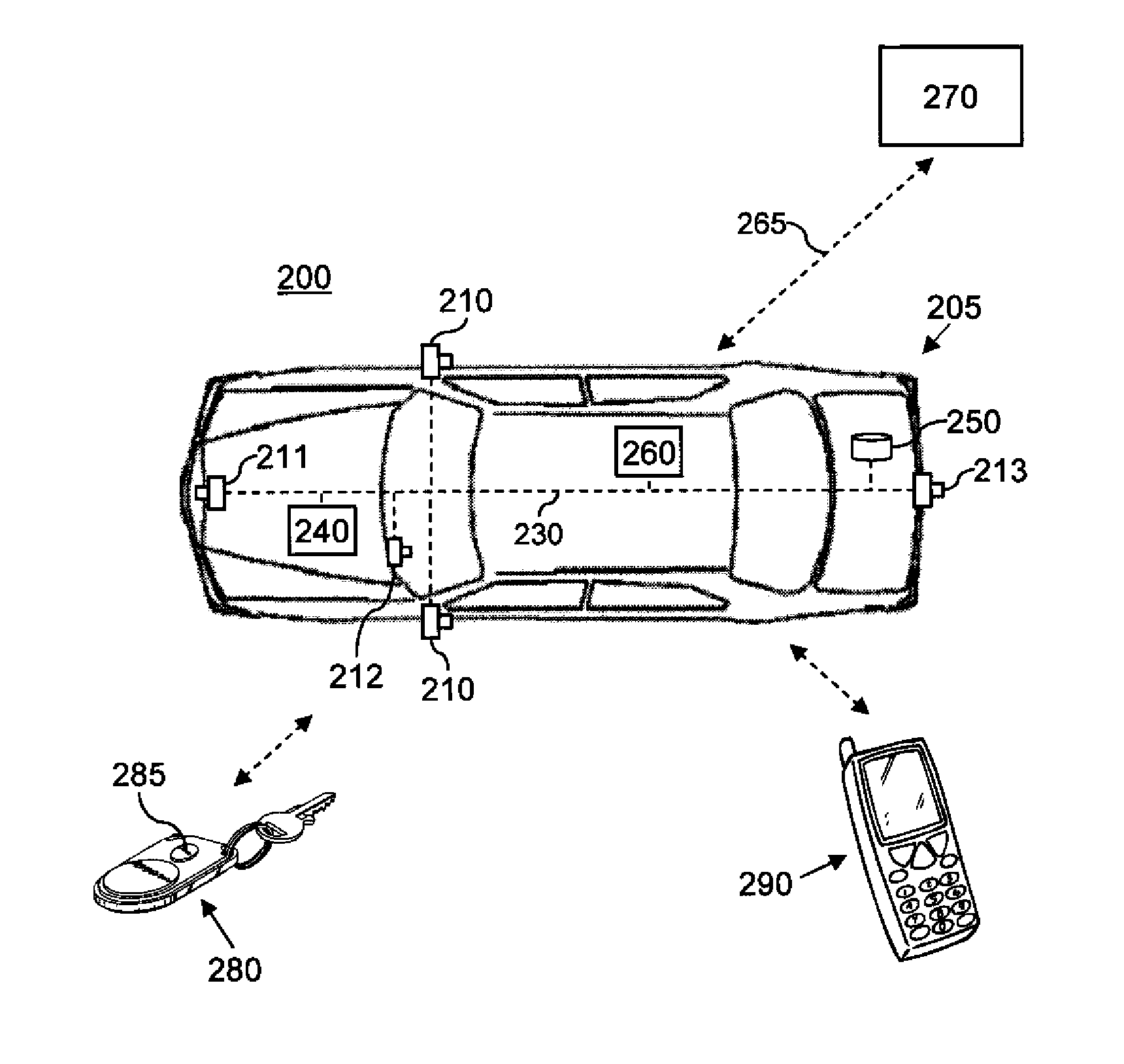
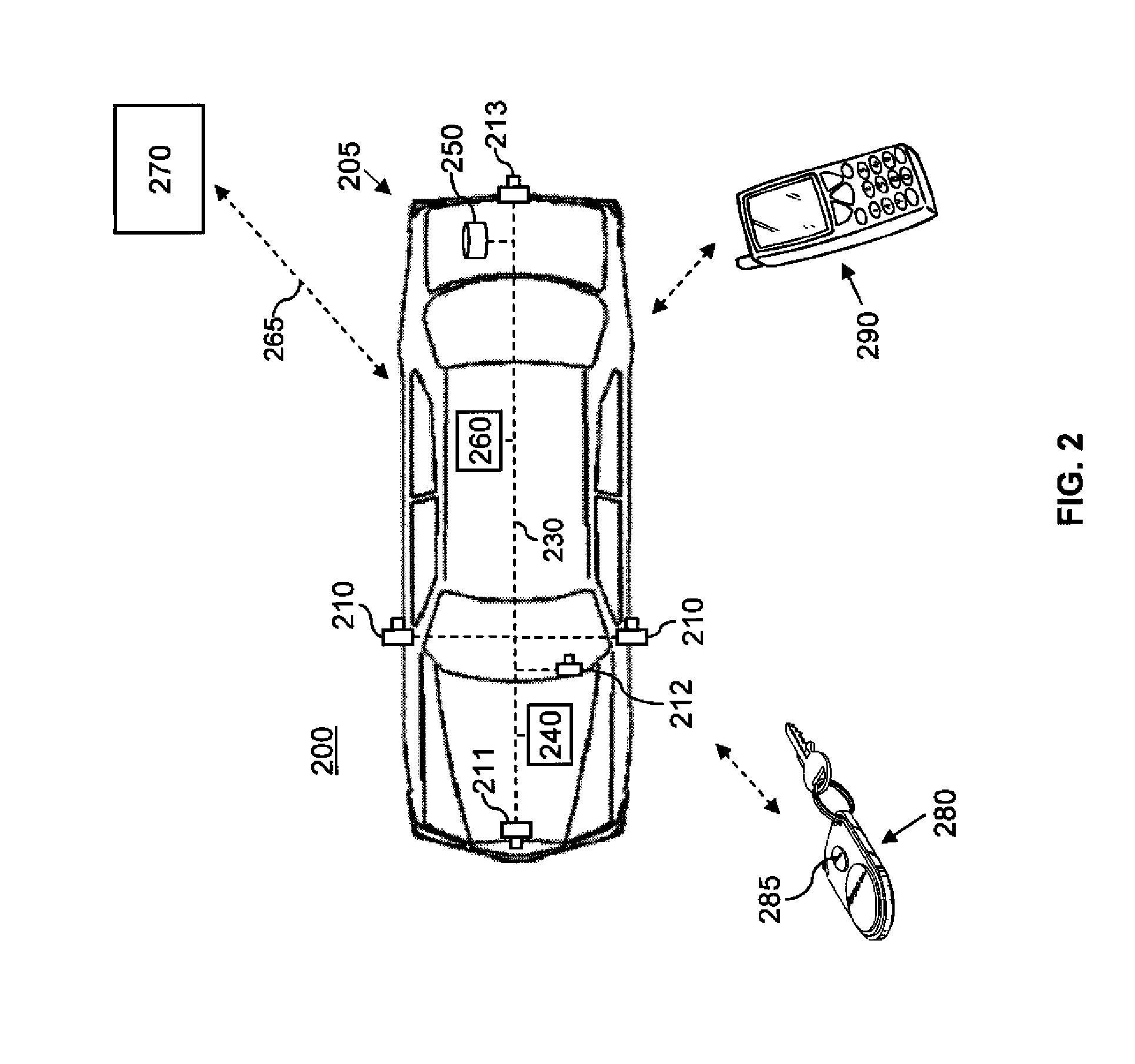
The present invention allows for the use of digital cameras in motor vehicles to capture exception events such as accidents, unauthorized usage, and security system events. This provides a cost advantage as the cameras can be used for multiple purposes. The transmitted digital images can be used to assess the status and medical needs of motor vehicle occupants, aid in the recovery of stolen or hijacked vehicles, and assist in identifying key information related to the causes and culprits of these exception events.

Problems solved by technology

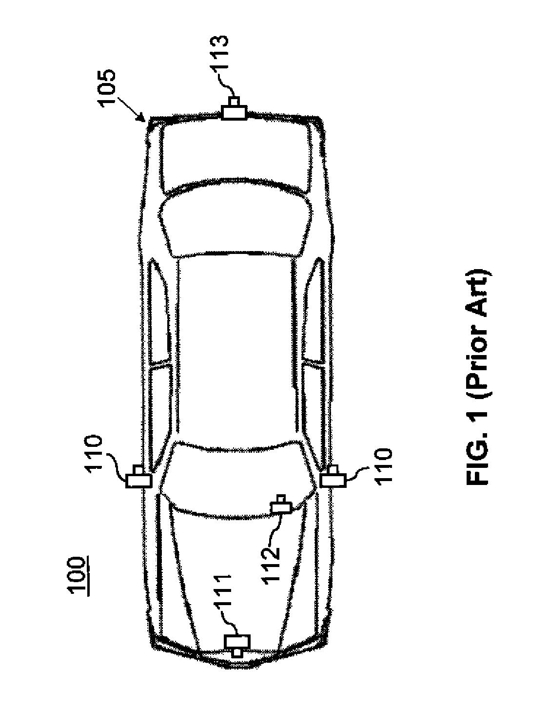
However, as with the machine vision applications, the digital images are generally not stored once they have been displayed.
Additionally, no provisions are made for multi-use of the one or more cameras mounted to the exterior of the vehicle or for flexible operation of the accident recording system.
This fixed and dedicated function is not cost effective.
While this solves the problem of high cost, it does not provide adequate coverage for all accidents since many accidents do not occur at intersections.
In these references the camera systems are specialized or dedicated systems, and are limited to imaging of the vehicle interior and activated only by forced entry or attempt at unauthorized use.
This has the disadvantage of moving all of the analysis and camera sub-system complexity to a central unit.
This would make the cost of the integrated system higher.

Method used


Image

  • Automotive imaging system for recording exception events
  • Automotive imaging system for recording exception events
  • Automotive imaging system for recording exception events

Examples


Embodiment Construction

[0039]Throughout the specification and claims, the following terms take the meanings explicitly associated herein, unless the context clearly dictates otherwise. The meaning of “a,”“an,” and “the” includes plural reference, the meaning of “in” includes “in” and “on.” The term “connected” means either a direct electrical connection between the items connected, or an indirect connection through one or more passive or active intermediary devices. The term “circuit” means either a single component or a multiplicity of components, either active or passive, that are connected together to provide a desired function. The term “signal” means at least one current, voltage, charge, or data signal.

[0040]Additionally, directional terms such as “on”, “over”, “top”, “bottom”, are used with reference to the orientation of the figure being described. Because components of embodiments of the present invention can be positioned in a number of different orientations, the directional terminology is used...


PUM


Abstract

A motor vehicle system for automatically reporting exception events, comprising: one or more digital cameras, at least one digital camera having a primary function; an image memory system for storing digital images; means for detecting exception events; and a wireless communications system for communicating with a central reporting service. A program memory stores executable instruction for causing a processor to perform the steps of: using at least one of the digital cameras to periodically capture digital images at a specified capture frequency; storing the periodically captured digital images in the image memory for a specified period of time; and receiving input from the means for detecting an exception event. In response to the detection of an exception event a communication link is opened to the central reporting service using the wireless communications system, and one or more of the captured digital images are transmitted to the central reporting service.

Description

FIELD OF THE INVENTION[0001]The invention relates generally to the field of automotive imaging systems employing digital cameras, and more particularly to a motor vehicle system that automatically transmits digital images in response to detecting an exception event.BACKGROUND OF THE INVENTION[0002]Many modern automobiles include integrated digital camera systems. Typical applications for these digital camera systems are blind spot monitoring, lane departure warning, rear view blind spot view, collision avoidance, traffic sign recognition, and drowsy driver detection. Typically, these systems incorporate visible or near infrared (NIR) capable image sensors.[0003]In many cases, the digital image data captured by the digital cameras is never rendered or viewed, but rather used in a machine vision system as information for making decisions. Once the digital image data has been analyzed and a decision has been made, the digital image data is generally discarded. The hardware and software...

Claims


Application Information

Patent Timeline
Patent Type & Authority Patents(United States)
IPC IPC(8): H04N9/47H04N7/18
CPCG07C5/085B60R25/102G07C5/008G07C5/0866G07C5/0891G08B13/19647G08B13/19671G08B13/19697G08B25/016
Inventor ERHARDT, HERBERT J.GUIDASH, ROBERT M.
Owner MONUMENT PEAK VENTURES LLC
Learn More