
Input control apparatus and method with inrush current, under and over voltage handling

a technology of input control and inrush current, which is applied in the direction of electrical equipment, dc-dc conversion, power conversion systems, etc., can solve the problems of internal limitation of upstream power converters, difficult to source or start up devices with large capacitances, and difficult to achieve relative high current levels with a single power converter, etc., to achieve high capacitance density, improve reliability, and improve efficiency

Active Publication Date: 2014-11-11
CRANE ELECTRONICS INC
View PDF84 Cites 15 Cited by
  • Summary
  • Abstract
  • Description
  • Claims
  • Application Information

AI Technical Summary

Benefits of technology

The control circuits described in this patent can effectively limit the initial surge of current when a device is powered up, which can protect components from damage and improve reliability. This is achieved by monitoring a signal that is proportional to the input current of the device. The approach does not require direct sensing of the input current, which results in higher efficiency and simpler circuit design. The control circuits can also be used in power converters to prevent power-on reset events or other non-monotonic startup issues. Overall, these circuits provide a reliable and efficient solution for limiting inrush current and other current-related issues.

Problems solved by technology

These relatively high current levels may be difficult to achieve with a single power converter.
However, upstream devices (e.g., power converters) may not be able to source or start up devices with large capacitances.
Often times, upstream power converters are internally limited, and enter a “hiccup” mode or repeatedly restart when faced with a large capacitive load.
These approaches to sensing the actual input current waveform lead to a substantial power loss, complicated designs, and / or high costs to address electrical isolation requirements, as well as slow transient response.
However, such an approach adds significant cost, requires added circuitry to amplify the signal, and is only applicable in AC current sensing applications.
Thus, this approach is only useful for very high AC current applications.
Thus, the various approaches require a number of tradeoffs due to design issues.
For example, approaches which employ a permanently placed resistor to limit inrush current suffer from a substantial decrease in efficiency.
It is typically difficult to derive an accurate input current signal without degrading the overall efficiency.
Signal integrity degradation resulting from common mode noise / current is also a problem.
Further, many approaches have had difficulty in maintaining fast transient response.

Method used


Image

  • Input control apparatus and method with inrush current, under and over voltage handling
  • Input control apparatus and method with inrush current, under and over voltage handling
  • Input control apparatus and method with inrush current, under and over voltage handling

Examples


Embodiment Construction

[0037]In the following description, certain specific details are set forth in order to provide a thorough understanding of various disclosed embodiments. However, one skilled in the relevant art will recognize that embodiments may be practiced without one or more of these specific details, or with other methods, components, materials, etc. In other instances, well-known structures associated with power conversion topologies have not been shown or described in detail to avoid unnecessarily obscuring descriptions of the embodiments.

[0038]Unless the context requires otherwise, throughout the specification and claims which follow, the word “comprise” and variations thereof, such as, “comprises” and “comprising” are to be construed in an open, inclusive sense, that is as “including, but not limited to.”

[0039]Reference throughout this specification to “one embodiment” or “an embodiment” means that a particular feature, structure or characteristic described in connection with the embodimen...


PUM


Abstract

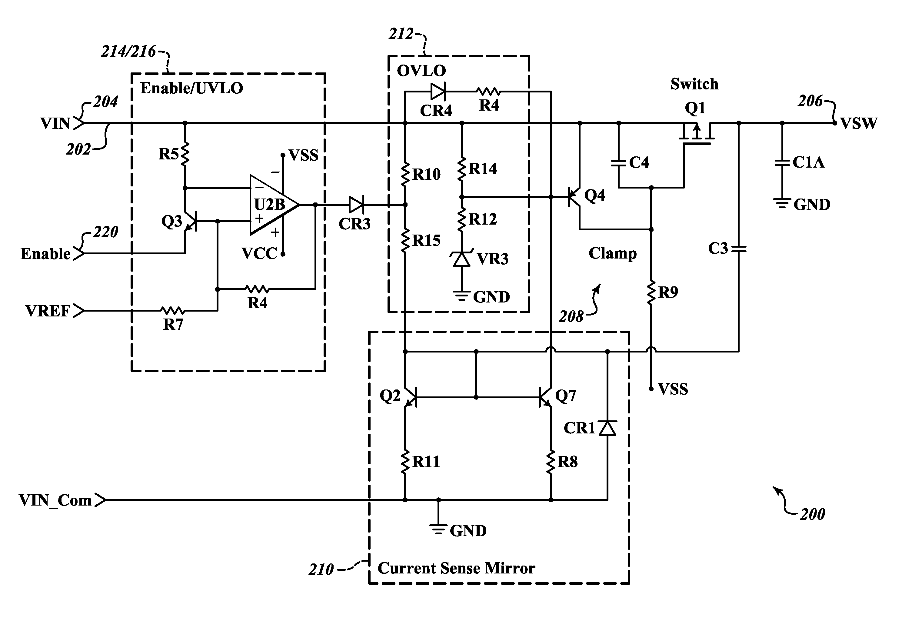
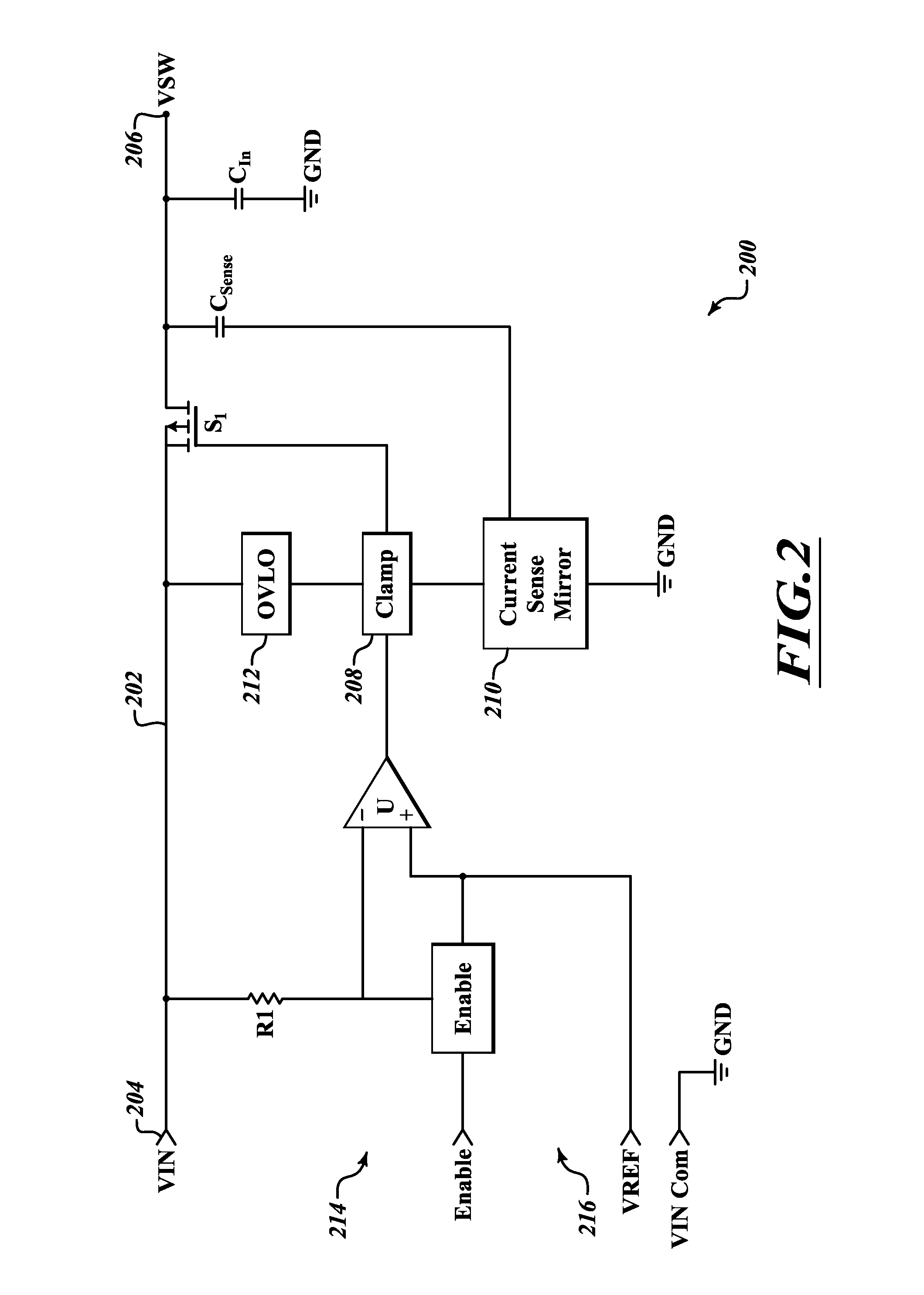
Control circuitry handles inrush current, and may provide under voltage and / or over voltage monitoring and handling, as well as remote enable handling. The circuitry may advantageously employ a sense capacitor in parallel with an input capacitor (e.g., bulk input filter capacitor), and a current mirror to produce a signal proportional to input current. A clamp circuit may control a series pass device to regulate current in response to the proportional signal, or to interrupt current flow in response to an under voltage or over voltage condition or receipt of a signal indicative of a disable state. An enable signal may be summed into a comparator that handles under voltage condition determination.

Description

BACKGROUND[0001]1. Technical Field[0002]This disclosure is generally input control to handle input current, and in particular to handle inrush current, and under voltage and over voltage conditions. Such may, for example be useful in a wide variety of devices or systems, particularly those with relatively large input capacitors, for example power converters, such as regulated switched mode power converters with bulk input filter capacitors.[0003]2. Description of the Related Art[0004]Power converters are used to transform electrical energy, for example converting between alternating current (AC) and direct current (DC), adjusting (e.g., stepping up, stepping down) voltage or potential levels and / or frequency.[0005]Power converters take a large variety of forms. One of the most common forms is the switched-mode power converter or supply. Switched-mode power converters employ a switching regulator to efficiently convert voltage or current characteristics of electrical power. Switched-...

Claims


Application Information

Patent Timeline
Patent Type & Authority Patents(United States)
IPC IPC(8): H02H9/02H02H3/20H02H3/24H02M1/36H02H3/087H02M1/32
CPCH02H3/087H02H9/025H02M1/32H02H3/24H02H3/202H02M1/36H02M3/156H02H9/001
Inventor WALTMAN, BARRY F.HUGHES, RODNEY ALANADRIANCE, REIDNKEI, BERTRANDKUEHNY, JAY ALLEN
Owner CRANE ELECTRONICS INC
Learn More