Doubly-fed generator and doubly-fed electric machine

a generator and double-fed technology, applied in the direction of electric generator control, machines/engines, mechanical equipment, etc., can solve the problems of inability to sustain the continued supply of electricity to consumers, economic difficulty in secure, and overcurrent capability and exciter ceiling voltage, so as to maximize the operation continuation capability of the generator, minimize torque fluctuations, and ensure the effect of stable grid operation

Active Publication Date: 2014-11-25
HITACHI IND PROD LTD
View PDF11 Cites 17 Cited by
  • Summary
  • Abstract
  • Description
  • Claims
  • Application Information

AI Technical Summary

Benefits of technology

[0021]A further object of this invention is to provide a doubly-fed variable-speed electric machine having the function of the doubly-fed motor / generator described above. Upon detection of an excitation overcurrent caused by a power grid fault, gates to the self-turn-off power devices in the largest phase and the second largest phase in terms of three-phase excitation current absolute value are fixed so as to prevent possible failures of the power devices due to switching. As to the remaining minimum current phase, when its absolute current value is equal to or less than a preset value, the gates of the self-turn-off power devices in that phase is pulse-width-modulated with a constant conduction ratio; and when its absolute current value is higher than the preset value, the gates are fixed to on-state or off-state. The use of this gate pattern prevents a short-circuit across the DC capacitor until power grid disturbances converge to a point where the excitation currents for all three phases fall below the preset value, at which time the PWM control is resumed by using the normal pulse commands from the excitation current controller.
[0022]Then, the polarity of the detected current value of the largest-current phase is checked. The firing pulse to either the power device P1 or N1 is fixedly held to on-state and that of the other to off-state to charge the DC capacitor. This allows the current to flow in a direction that charges the DC capacitor at all times, thus preventing a loss of DC voltage.
[0025]Therefore, the objective of this invention is achieved by providing the excitation overcurrent detection unit for a doubly-fed generator / motor with a function of checking an excitation current magnitude relationship among three phases, fixing a firing pulse so as to cause the largest-current phase and the second-largest-current phase to charge the DC capacitor through diode operation, controlling the conduction ratio of the third-largest-current phase according to its detected current value to protect against a short-circuit across the DC capacitor and, when the voltage of the DC capacitor exceeds a preset value, suppressing the voltage value by active or passive devices.
[0027]In the event of a voltage fall caused by a lightning-induced ground fault in a power grid in particular, the doubly-fed generator of this invention can contribute to a stable operation of the grid by minimizing torque fluctuations in the doubly-fed generator and at the same time maximizing the operation continuation capability of the generator.

Problems solved by technology

As to the power converter for secondary excitation, not only does it have a far larger capacity than that of the excitation power converter for the conventional synchronous machine, though its capacity can be made smaller than that of an armature of the generator, its circuit is more complex.
Therefore an overcurrent capability and an exciter ceiling voltage, equivalent to those of the excitation power converter of the conventional synchronous machine, are both economically difficult to secure.
As a result, even if the generator can be managed to remain in operation, the large and rapid changes in the torque cause significant disturbances in the power grid, making it impossible to sustain the continued supply of electricity to consumers.
On the other hand, when used on doubly-fed generators that are required to continue their operation even during abnormalities on the power grid side, the power converters using the self-turn-off power devices have difficulty securing a short-time overcurrent capability economically.

Method used


Image

  • Doubly-fed generator and doubly-fed electric machine
  • Doubly-fed generator and doubly-fed electric machine
  • Doubly-fed generator and doubly-fed electric machine

Examples


embodiment 1

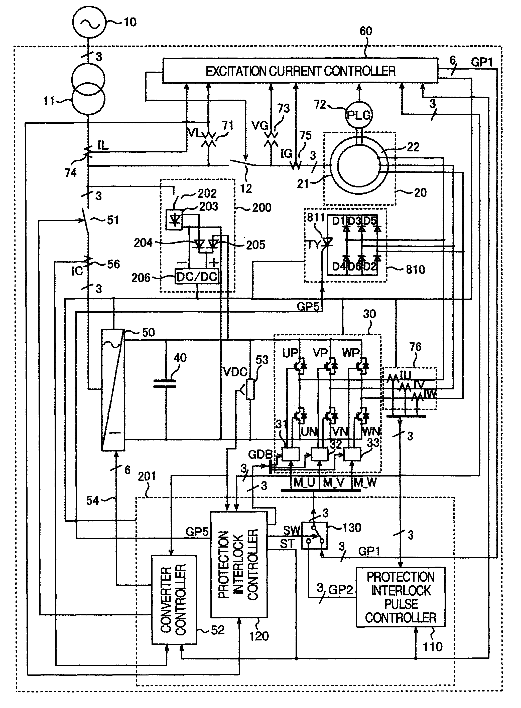
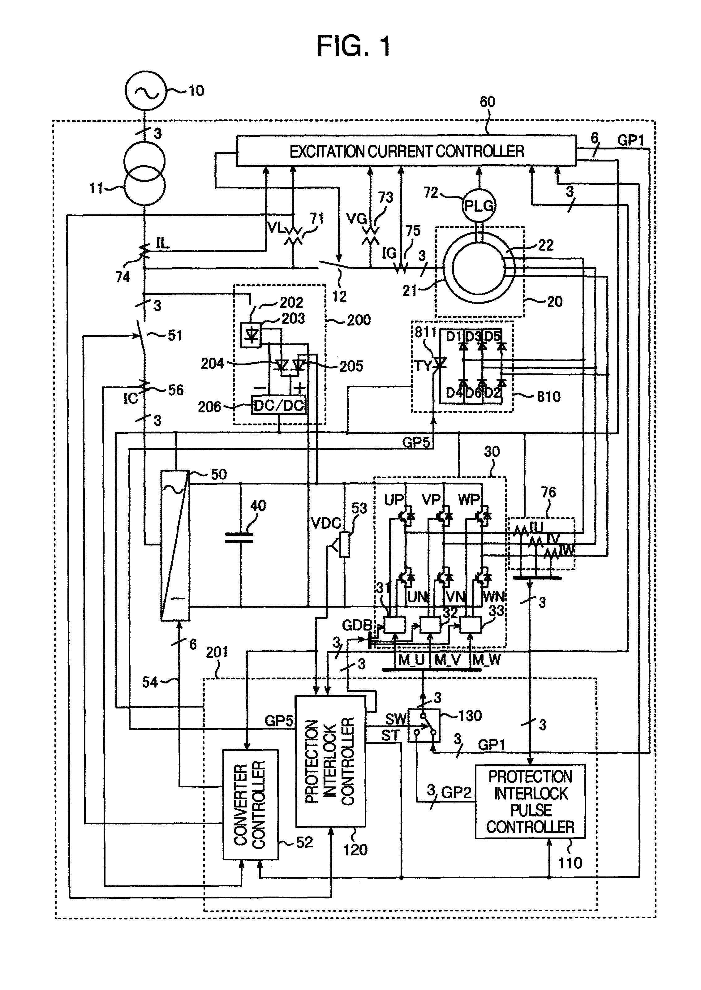
[0040]The configuration of embodiment 1 according to this invention will be explained by referring to FIG. 1.

[0041]In this embodiment, as a doubly-fed generator, a doubly-fed electric machine commonly used in a wind power generation system is employed, with a stator side armature winding 21 of a wound-rotor induction machine connected to a power grid 10 through a transformer 11 and a circuit breaker 12.

[0042]A first power converter 30 has six three-phase bridge connected arms (UP, VP, WP, UN, VN, WN), each made up of anti-parallelly connected self-turn-off power device and diode, and is controlled to turn on and off by pulse width modulation commands (M_U, M_V, M_W). A capacitor 40 is connected between DC side terminals of the first power converter 30. The internal configuration of the first power converter 30 will be described later referring to FIG. 10.

[0043]A second power converter 50 has its DC side terminals connected to both ends of the capacitor 40 and its AC side terminals c...

embodiment 2

[0079]FIG. 6 shows a second embodiment of this invention.

[0080]A resistor 310 and a self-turn-off device 320 (CHV) form a circuit to minimize a voltage increase in the DC circuit. When the DC voltage VDC exceeds a preset value VD1, a firing command GP3 from a protection interlock controller 140 is turned on to lower the voltage. When the DC voltage goes below a preset value VD2, the GP3 is turned off. This arrangement allows the operation to continue even when the energy, which is triggered by GP2 to flow in from the rotor circuit 22 of the wound-rotor induction machine, fails to be released to the grid side by the control of the second power converter, resulting in a voltage increase.

[0081]A non-linear resistor 410 using a zinc oxide device is able to suppress a voltage increase in a DC circuit and may be used in place of the resistor 310 and the self-turn-off device 320 (CHV) or in combination.

[0082]FIG. 6 represents an example in which the non-linear resistor 410 is connected wit...


PUM


Abstract

The excitation overcurrent detection unit for the doubly-fed electric machine is provided with a function to determine an excitation current magnitude relationship among three phases. The firing pulse is held to on-state or off-state to cause the largest-current phase and the second-largest-current phase to charge the DC capacitor by the operation of diodes. The conduction ratio of the third-largest-current phase or minimum current phase is controlled according to the detected current value to protect against a possible short-circuit across the DC capacitor. When the voltage of the DC capacitor exceeds a preset value, the voltage is suppressed by operating active or passive power devices.

Description

BACKGROUND OF THE INVENTION[0001]The present invention relates to a doubly-fed motor / generator using an excitation power converter or to a doubly-fed electric machine.[0002]A doubly-fed generator using an excitation power converter, or a doubly-fed variable-speed electric machine is able to control a reactive power output, as does a conventional synchronous generator / motor, and also to realize a high-speed torque control or a high-speed active power control within a rotation speed range around a synchronous speed. This gives the doubly-fed electric machines an advantage of being able to optimally operate prime movers, such as hydraulic power plants and wind power generation systems, in a wider range of conditions than can the conventional synchronous machines. They have another advantage of being able to contribute to stabilizing the frequency of the utility power system or power grid by temporarily releasing or absorbing energy of a rotating flywheel to and from the power grid.[000...

Claims


Application Information

Patent Timeline
Patent Type & Authority Patents(United States)
IPC IPC(8): H02P27/08H02J3/00H02P9/00
CPCH02P9/102H02P9/007H02P2009/003H02H1/00H02P2009/004H02H7/065H02P2101/10H02P2101/15
Inventor BANDO, AKIRAICHINOSE, MASAYAKIYOFUJI, YASUHIRONAKAYAMA, YASUAKI
Owner HITACHI IND PROD LTD
Why Eureka
Try Eureka