
Apparatus and method for clock shift correction for measurement-while-drilling measurements

a technology of clock shift and measurement, applied in the field of downhole measurement correction, can solve the problems of affecting the accuracy of the final log, erroneous depth placement of the measurement, and the use of downhole clocks in relatively harsh environments

Active Publication Date: 2014-12-02
BAKER HUGHES INC
View PDF30 Cites 10 Cited by
  • Summary
  • Abstract
  • Description
  • Claims
  • Application Information

AI Technical Summary

Benefits of technology

The patent describes a method and system for accounting for drift in a downhole clock during wellbore operations. The method involves taking measurements during drilling and transmitting signals between a surface location and the bottom of the wellbore using telemetry. The signals are recorded using a clock associated with the location where they were recorded. The recorded signals are then used to align the downhole measurements with the wellbore depth and correct any drift in the downhole clock. The system includes a telemetry system for generating and receiving signals between the surface and the bottom of the wellbore, which may be mud pulse telemetry, acoustic telemetry, electromagnetic telemetry, or other suitable telemetry system. The recorded times and other data may be stored in a memory device or disk. The technical effect of the patent is to provide a more accurate and reliable method for accounting for drift in downhole clocks during wellbore operations.

Problems solved by technology

This affects the accuracy of the final logs.
Downhole clocks are used in relatively harsh environments (high temperature, pressure and vibration) and often drift over time.
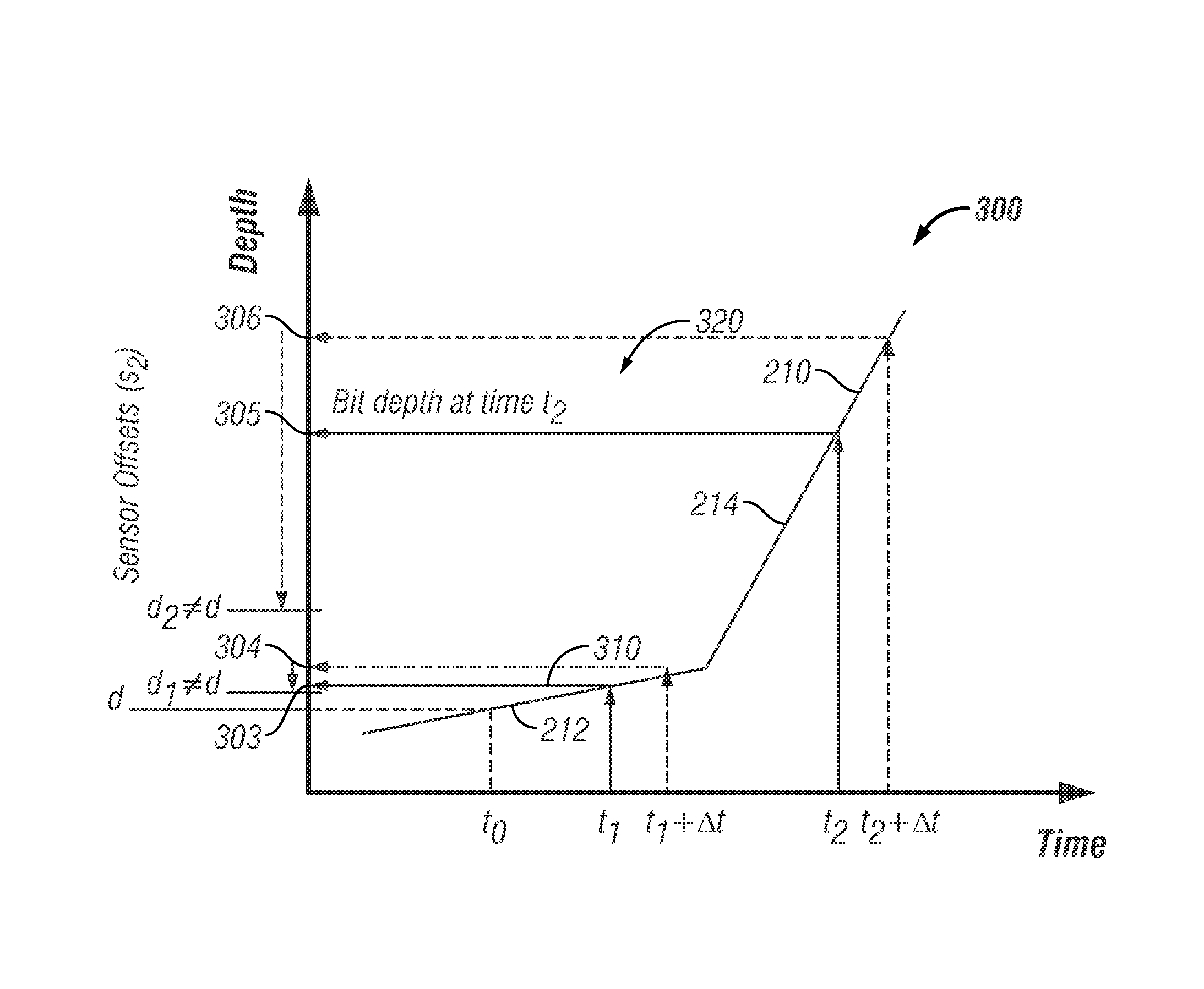
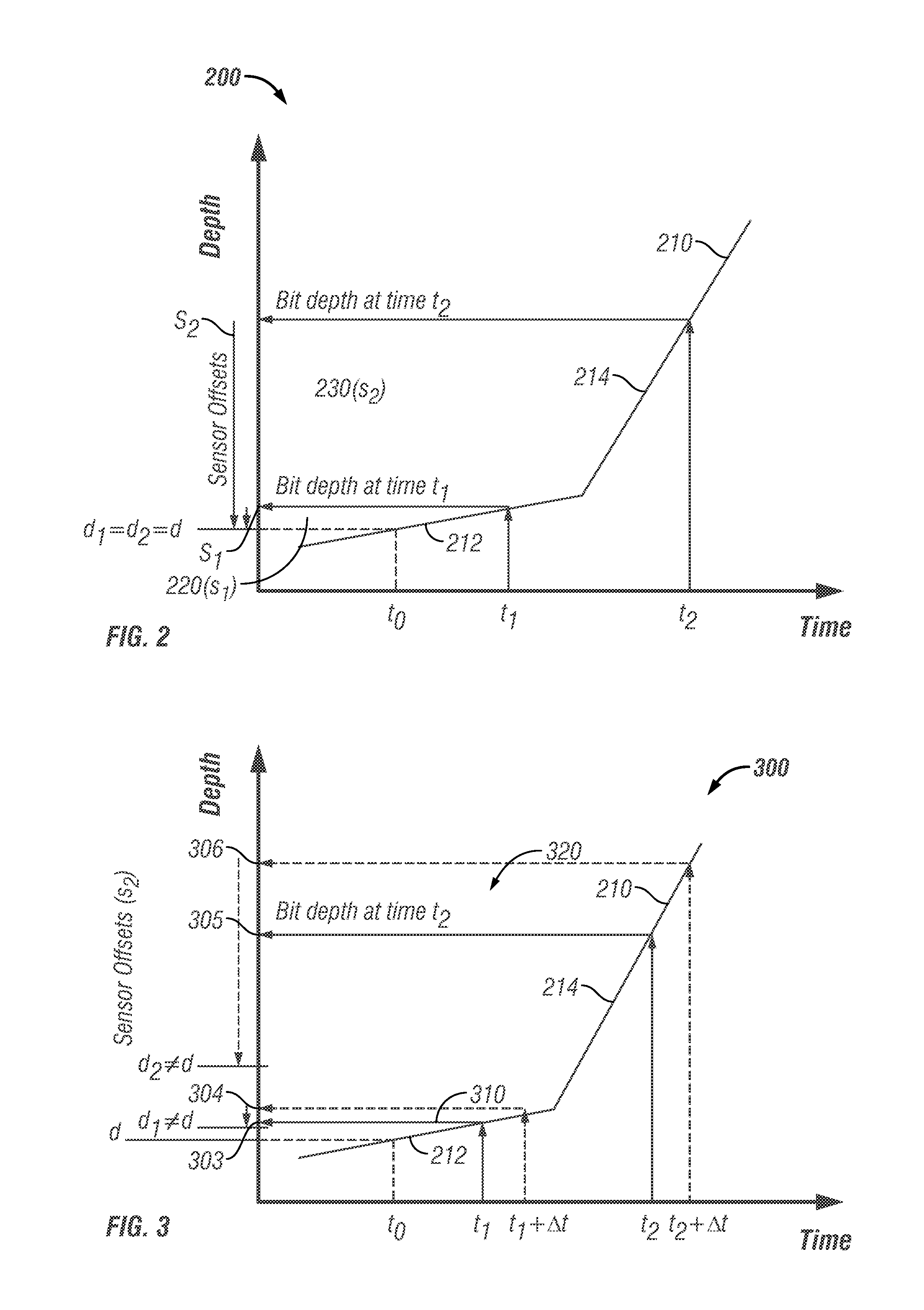
When the tool or downhole clock does not produce the same time as the surface clock during the entire drilling run, any attempt to use time-depth profiles (which are based on the surface clock time) to convert from when to where can result in erroneous depth placement of the measurement.
Due to the non-linearity of the time-depth transformation, even a relatively small time drift can result in noticeable errors or in unacceptable logs.
Such methods may produce less than acceptable correction results as the clock drift may be nonlinear over the drilling run.

Method used


Image

  • Apparatus and method for clock shift correction for measurement-while-drilling measurements
  • Apparatus and method for clock shift correction for measurement-while-drilling measurements
  • Apparatus and method for clock shift correction for measurement-while-drilling measurements

Examples


Embodiment Construction

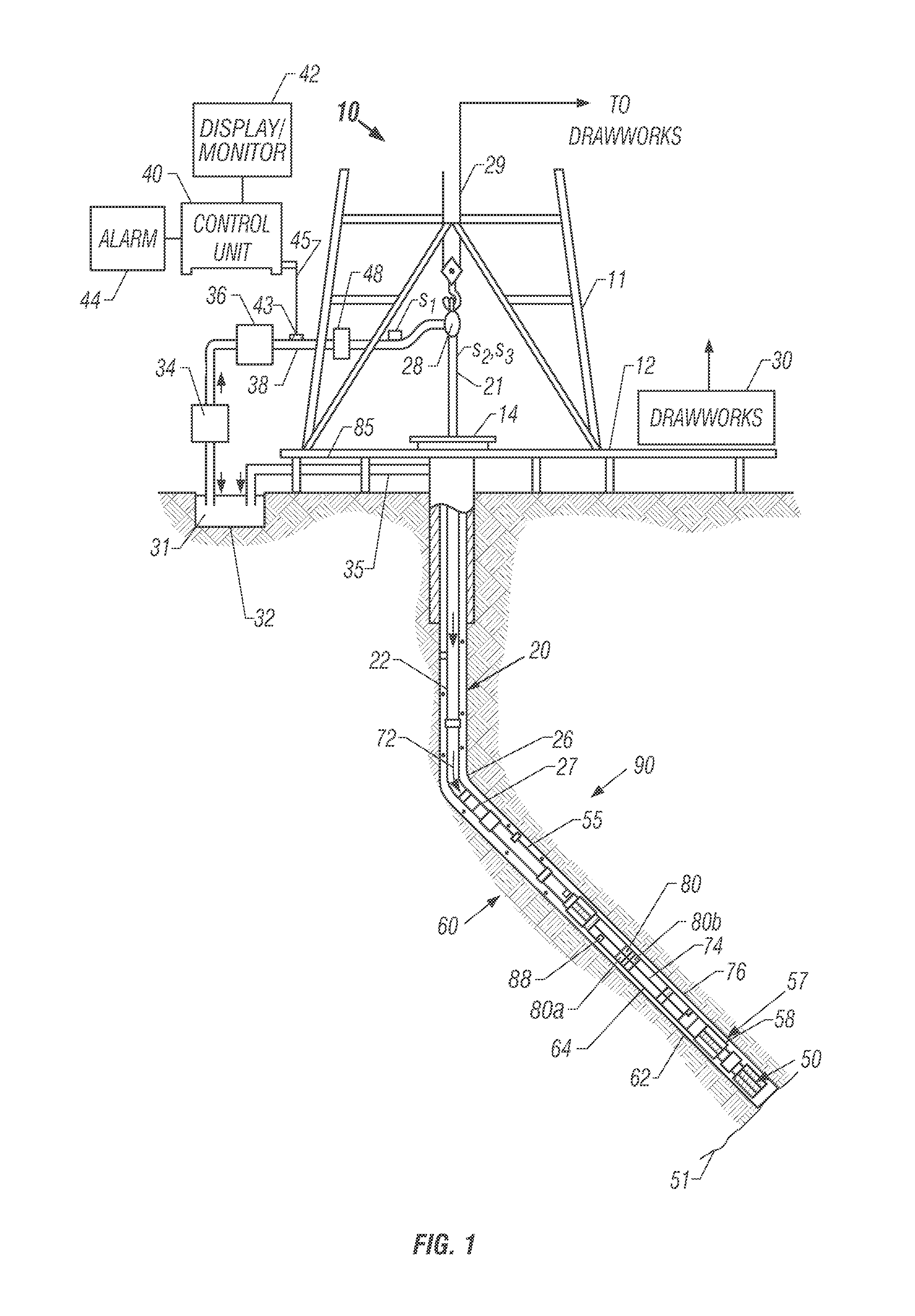
[0022]FIG. 1 shows a schematic diagram of a drilling system 10 according to one embodiment of the disclosure that includes a drillstring 20 having a drilling assembly 90, also referred to as a bottomhole assembly (BHA), conveyed in a borehole 26 for drilling a wellbore 26 in an earth formation. The drilling system 10 includes a conventional derrick 11 erected on a floor 12 that supports a rotary table 14 that is rotated by a prime mover, such as an electric motor (not shown), at a desired rotational speed. The drillstring 20 may include drilling tubulars 22 (such as a drill pipe) sections. A drill bit 50, attached to the end of the BHA 90, disintegrates the geological formations 60 when it is rotated to drill the borehole 26. The drillstring 20 is coupled to a drawworks 30 via a kelly joint 21, swivel 28 and line 29 through a pulley. During the drilling operations, the drawworks 30 is operated to control the weight on bit (WOB), which affects the rate of penetration (ROP). The opera...


PUM


Abstract

The disclosure provides a method which includes transmitting signals over a time period between a downhole location and a surface location during drilling of a wellbore; recording the time of each signal at the surface using a surface clock and the time of each signal downhole using a downhole clock; and correcting the downhole measurements using the recorded times.

Description

CROSS REFERENCE TO RELATED APPLICATIONS[0001]The present application claims priority from U.S. Provisional Application 60 / 868,854, filed on Dec. 6, 2006.BACKGROUND OF THE DISCLOSURE[0002]1. Field of the Disclosure[0003]The disclosure herein relates generally to correcting downhole measurements for clock drifts.[0004]2. Description of the Related Art[0005]To drill wells, such as hydrocarbon wells, a drill bit located at the end of a drillstring is rotated to drill into the formation. The rate of penetration (ROP) depends upon the weight on bit (WOB), the rotary speed of the drill bit, the type of the formation and the condition of the drill bit. The drill bit is attached to the bottom end of bottomhole assembly (BHA) that includes several formation evaluation (FE) tools or sensors that make measurements of formation properties. These tools include, for example, tools for determining density, porosity, resistivity, acoustic, nuclear and other properties of the formation surrounding th...

Claims


Application Information

Patent Timeline
Patent Type & Authority Patents(United States)
IPC IPC(8): G01V1/40E21B47/00G01V11/00
CPCG01V11/002G01V2200/12E21B47/00E21B47/12G01V1/42
Inventor DASHEVSKIY, DMITRIYMCGINLEY, PATRICK J.MACPHERSON, JOHN D.BROOKS, ANDREW G.DAHL, THOMAS G.PINNELL, MITCHELL G.CAIRNS, PAUL GERARDRANDALL, ROBIN F.HILL, MARK ANDREWROBNETT, EDWARD W.
Owner BAKER HUGHES INC
Learn More