Supercharge Your Innovation With Domain-Expert AI Agents!

Method and device for logging the fluid depth in a wellbore

a wellbore and fluid depth technology, applied in the field of wellbore fluid depth logging, can solve the problems of unfavorable oil pumping operation withdrawal, increase the extraction rate, and pose a possible danger, and achieve the effect of elegant possibility and robust vibrator

Active Publication Date: 2014-12-02
ROHOL AUFSUCHUNGS
View PDF26 Cites 25 Cited by
  • Summary
  • Abstract
  • Description
  • Claims
  • Application Information

AI Technical Summary

Benefits of technology

The invention is a method and device that can measure and display the depth of fluid in oil and gas extraction sites or deep drillings continuously and automatically. This allows for a continuous knowledge of the fluid depth, which can contribute to optimizing oil and gas production. The use of a membrane as an element of the signal emitter or vibration-emitting device results in increased sensitivity and detection of more echoes. Overall, the invention offers improved efficiency and accuracy in measuring fluid depth.

Problems solved by technology

For example, it is undesirable for the oil pumping operation to withdraw more crude oil from the wellbore than can flow back into this wellbore from the deposit.
This would pose a possible danger as extraction continues.
On the other hand, if the fluid depth rises, there exists the possibility of increasing the rate of extraction.
The location of the fluid depth in the wellbore can naturally be several hundred or even greater than 1000 m deep and is accordingly hard to log and determine from the ground surface.
In this case, the wellbore may not have any major discontinuities that act as strong reflectors for the emitted signal and therefore lead to interference with the result.
This abrupt expansion of the gas present in the wellbore into the pipe also generates an impulse having a very steep and high front flank.
However, the speed of sound in the wellbore is not known, because a complicated gas mixture, which, moreover, is not constant in time and which consists of, among other things, methane, nitrogen, carbon dioxide, argon, and many other gases, is present in the wellbore between the ground surface and the fluid depth and behaves in no way like an ideal gas and also changes in composition both with time and over the depth of the wellbore in an unforeseeable manner.
This means that it is not possible to deduce automatically the distance of travel of a sound wave from its time of travel and it is not yet possible to make a quantitative statement about the distance of the path traveled from the time of travel of the sound wave from the ground surface to the fluid depth and, after reflection, back to the ground surface.
A problem is that there are multiple reflections, because each sound wave that reflects at a joint and travels upward is partially reflected anew at all of the above-lying joints and these doubly reflected sound waves travel downward and result in additional triple and multiply reflected sound waves that impinge at the ground surface due to renewed reflection and interfere with and appreciably hamper the identification of the reflection lines that are of actual interest.
The expense for signal generators that operate separately from one another and operate in separate regions of the wellbore cross section is appreciable.
In practice, this proposal has not gained acceptance.
Thus, in such measurements using methods of prior art, it is necessary to interrupt the drilling operation for the time of the measurement in many cases.
The arrangements of prior art are exacting and have to be used in places where the wellbores are located, which is often the case in impassable terrain that is not favorably located for vehicle access.

Method used


Image

  • Method and device for logging the fluid depth in a wellbore
  • Method and device for logging the fluid depth in a wellbore
  • Method and device for logging the fluid depth in a wellbore

Examples


Embodiment Construction

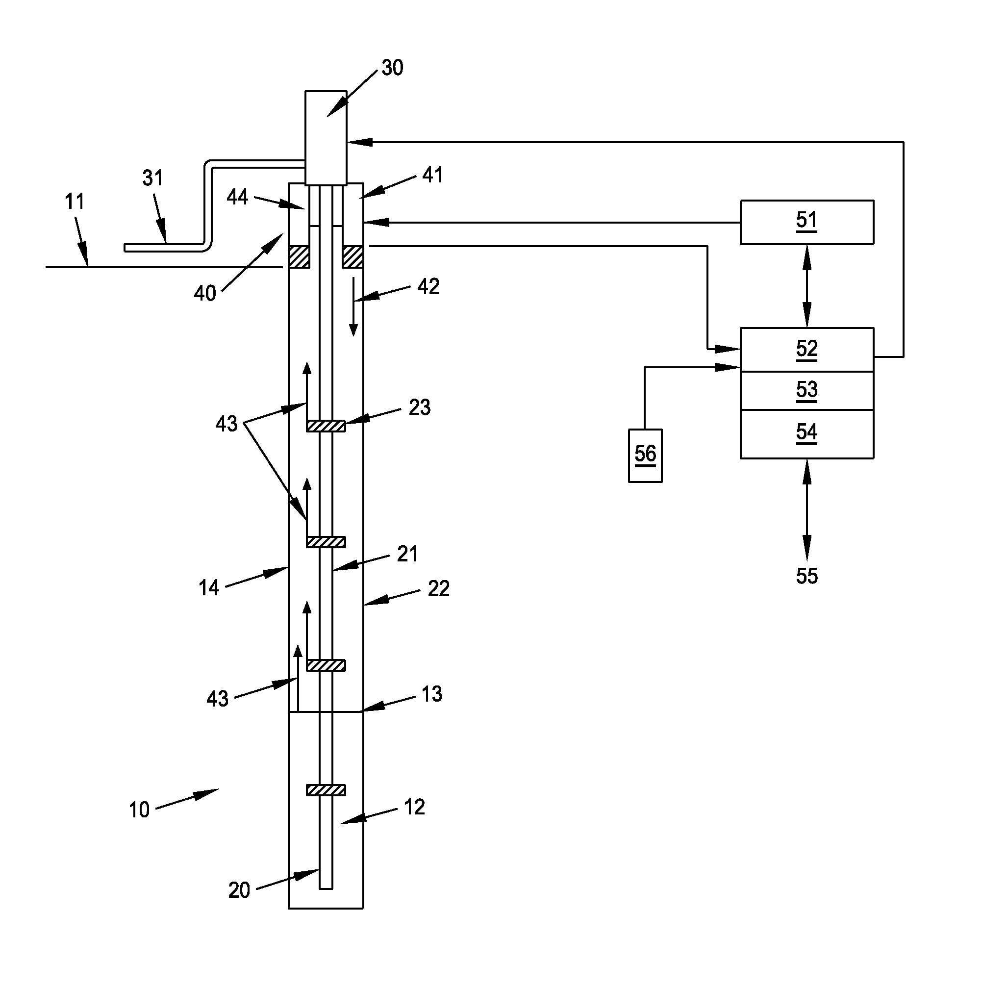
[0084]Illustrated in FIG. 1 is a wellbore 10. The wellbore 10 extends from the ground surface 11 downward to a deposit for crude petroleum or crude oil. The crude oil 12 forms, together with additional fluids, a mixture that is separated by a boundary layer 13 from the various gases and gaseous media 14 forming above it. These gases are, among others, nitrogen, argon, and other components of the atmosphere and, in addition, methane and other gases that form above the crude oil. The composition varies over the course of time and also with the depth of the wellbore 10.

[0085]The precise location of the boundary layer 13 between the fluid substances containing the crude oil 12 and the gaseous media 14 constitutes a fluid depth. The precise location of this fluid depth 13 or of the boundary layer varies over the course of time, depending on the rate at which the crude oil 12 and the other fluids enter the wellbore 10 from the side and from below.

[0086]In order to extract the crude oil 12...


PUM


Abstract

In a method for logging the location of a fluid depth in a wellbore, an acoustic event is allowed to take place in a specific manner at the ground surface. This acoustic event generates pressure waves. The pressure waves travel in the wellbore downward. The pressure waves traveling in the wellbore are reflected at least also at the fluid depth. At the ground surface, the pressure waves traveling there out of the wellbore are picked up and the time of travel since the acoustic event is measured. The picked-up and measured pressure waves are analyzed and, together with the associated time of travel, the location of the fluid depth is deduced. The acoustic event generates a signal pattern having a predetermined, time-variable frequency spectrum. The signal pattern is emitted as vibration event into the wellbore, travels downward, and is reflected. At the ground surface, the picked-up signals originating from the wellbore are analyzed. During the analysis, vibration events that do not correlate with the emitted signal pattern are filtered out. From the vibration events that are among the picked-up signals and correlate with the emitted signal pattern and from the time of travel since the radiation of the signal pattern, the location of the fluid depth is deduced.

Description

FIELD OF THE INVENTION[0001]The invention relates to a method for logging the location of a fluid depth in a wellbore during deep drilling, in which an acoustic event is allowed to take place in a specific manner at the ground surface, said acoustic event generating pressure waves, in which the pressure waves generated by the event travel downward in the wellbore, in which the pressure waves traveling into the wellbore are reflected at least also at the fluid depth, in which pressure waves traveling out of the wellbore to the ground surface are picked up there and the time of travel since the acoustic event is measured, in which the picked-up and measured pressure waves are analyzed and used, together with the associated time of travel, to determine the location of the fluid depth, and a device for determining the fluid depth in wellbores by using such a method.BACKGROUND OF THE INVENTION[0002]Wellbores serve, in particular, for discovering crude oil or natural gas and extracting it...

Claims


Application Information

Patent Timeline
Patent Type & Authority Patents(United States)
IPC IPC(8): G01V1/44G01V1/40G01F23/296E21B47/04
CPCG01V1/44G01F23/2962E21B47/042E21B47/047
Inventor ZAMOW, RAINERSONNLEITNER, KURT
Owner ROHOL AUFSUCHUNGS
Features
  • R&D
  • Intellectual Property
  • Life Sciences
  • Materials
  • Tech Scout
  • Unparalleled Data Quality
  • Higher Quality Content
  • 60% Fewer Hallucinations
Learn More