Photo-responsive layer and layer assembly

a photo-responsive layer and layer technology, applied in the direction of material analysis using wave/particle radiation, material analysis by optical means, instruments, etc., can solve the problems of unsafe drinking water production and consumption, and achieve the effect of reducing production costs and increasing topographical differences

Inactive Publication Date: 2014-12-30
KONINK PHILIPS ELECTRONICS NV
View PDF5 Cites 5 Cited by
  • Summary
  • Abstract
  • Description
  • Claims
  • Application Information

AI Technical Summary

Benefits of technology

[0014]By using such second material, a photo-responsive layer may be provided which provides increased possibility of controlling the geometrical shape of the layer using photo-activating illumination. For example, when exposed to photo-activating illumination, protrusions may be formed in the first domains, and recessions may be formed in the second domains, or vice versa. Preferably, the second material is a liquid crystal polymer material. By using liquid crystal polymer material in combination with a photo-responsive moiety also in the second domains, a wide range possibility of different topographies can be achieved. Hence, the molecular ordering can be varied depending on the technical application. For example, the second molecularly ordered phase may be a homeotropic phase. This is advantageous for example in combination with a first domain comprising a nematic phase, since the topography when exposed to photo-activating illumination hence would comprise increased topographical differences compared to using a second material not responsive to illumination. Preferably, the second domain is capable of a reverse geometrical change when the activating illumination is discontinued.
[0015]In some embodiments, it may be advantageous to use an isotropic phase in the second domain, i.e. the second molecularly ordered phase may be an isotropic phase. This is preferred for applications where sufficient geometric change is provided by the first domains. In these cases, it is not necessary to further functionalize the second domains and thereby for example the production costs can be lowered.
[0018]In embodiments of the invention, the photo-responsive layer assembly has a maximum average fluid path, or channel, diameter in the range of 0 to 1 μm, preferably 0 to 0.02 μm, when not under exposure to the photo-activating illumination. Thereby, the photo responsive layer assembly may either prevent flow of water, or function as a water filter which admits a flow of water, but which prevents contaminants such as viruses and / or bacteria to pass the layer assembly when not exposed to photo-activating illumination. Hence, the invention provides the possibility to use a system which when exposed to UV-radiation is open transmitting also biological species which are subsequently killed by the UV-radiation and which in absence of UV irradiation, allows water to flow through pores (or channels) which are so small that biological species are filtered out. In absence of UV-radiation, the water purification system thus still continues working but at a lower yield.

Problems solved by technology

In all these systems it is essential that the water supply stops as soon the UV source diminishes, otherwise unsafe drinking water may be produced and consumed.
When too low amount of UV-radiation is detected by the photochemical cell, the electromagnet is switched off, which results in that the metal ball in the valve instead covers the fluid inlet, so that no fluid can pass through the apparatus.
Especially at locations where use is made of sun light as UV source electricity is not always available.

Method used


Image

  • Photo-responsive layer and layer assembly
  • Photo-responsive layer and layer assembly
  • Photo-responsive layer and layer assembly

Examples


exemplary embodiment 1

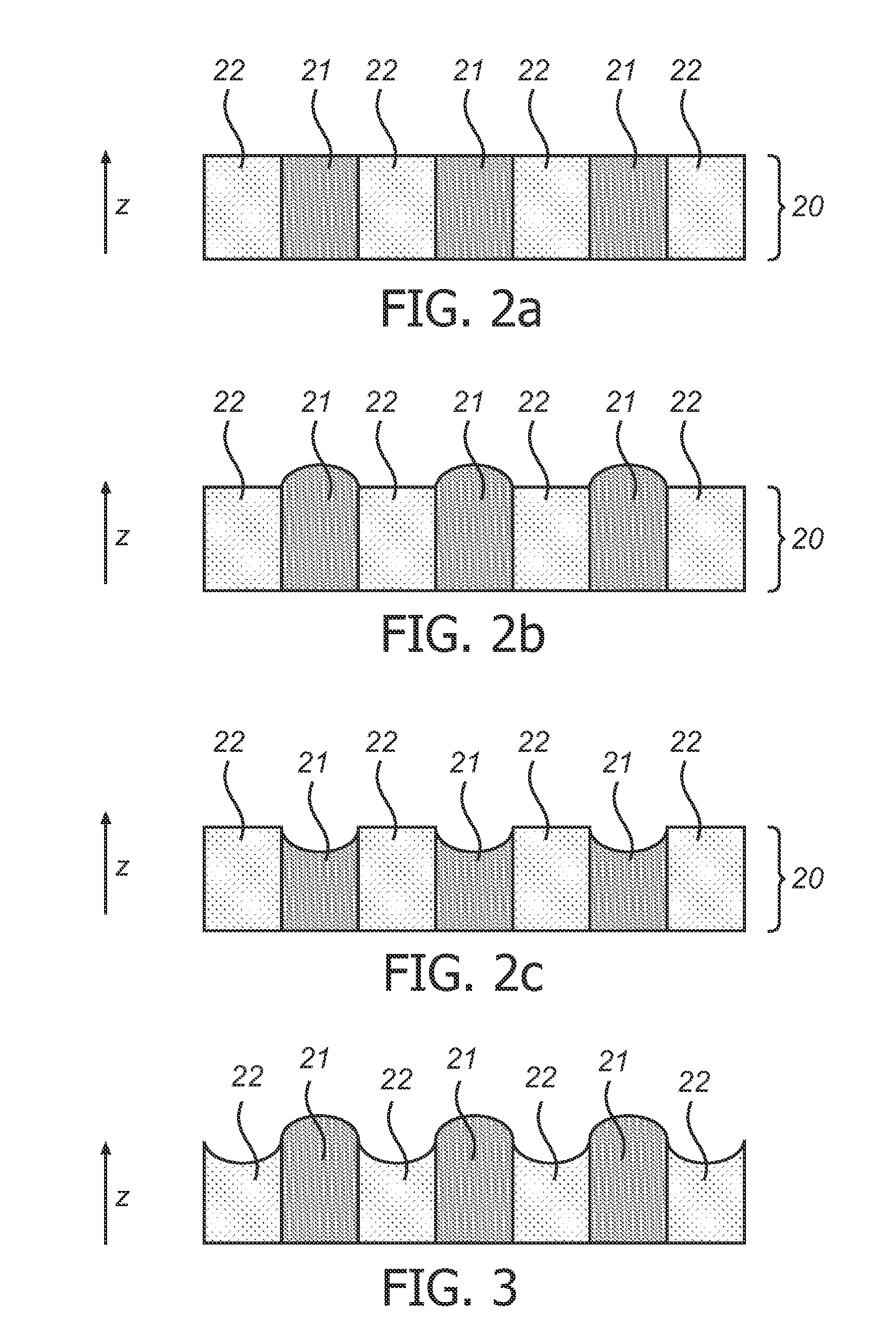
[0062]This embodiment corresponds to the photo-responsive layer of FIG. 2b, which is prepared by the production method described below. In this embodiment the photo-responsive layer comprises a material comprising first domains of a chiral nematic (cholesteric) structure, hence comprising alternating planarly oriented molecules and randomly oriented molecules. The areas of planarly oriented molecules form the first domains and the areas with randomly oriented molecules i.e. isotropic form the second domains. In this example, the same composition is applied over the surface of the substrate. The material of first domains and second domains contains a polymerized material based on the monomers and specific concentrations shown in Table 1.

[0063]

TABLE 1Chemical structures of the monomers used in embodiment 1Typical MaterialChemical structureconcentrationMonomer 110 to 90 wt. % More typically 20 to 50 wt. %Monomer 210 to 90 wt. % More typically 20 to 50 wt. %Monomer 310 to 90 wt. ...

exemplary embodiment 2

[0079]This embodiment corresponds to the photo-responsive layer in FIG. 3. This embodiment is similar to embodiment 1, with the difference that in the photo-responsive layer, the isotropic (randomly oriented) areas are replaced by areas with molecular order such that there is a preferential orientation of the molecules perpendicular to the surface (homeotropic orientation). As a result, the photo-induced surface deformation is larger and deformations >4 μm are obtained compared to embodiment 1.

[0080]Homeotropic areas are obtained by carrying out the second UV-exposure under an externally applied electrical field. The monomer composition is somewhat adjusted in order to obtain a larger dielectric anisotropy:[0081]28 wt.% monomer 1[0082]40 wt.% monomer 2[0083]16 wt.% monomer 3[0084]6 wt.% monomer 4[0085]8 wt.% monomer 5[0086]2 wt.% photo-initiator Irgacure 819

[0087]The photo-responsive assembly may be produced as described for Exemplary embodiment 1 and applied in a photo-responsive l...

exemplary embodiment 3

[0088]This embodiment corresponds to the photo-responsive layer in FIG. 2b. In this embodiment the photo-responsive layer is made by filling a grid obtained from a lithographic material with the monomer mixture of embodiment 1. The grid can for instance be made from SU-8 (microchem) on a substrate containing an alignment layer to assure the formation of a chiral nematic order with planar alignment. An example of such a grid and a schematic representation of making the photo-responsive layer according to the third embodiment are shown in FIGS. 6a and b.

[0089]The preparation of the photo-responsive layer according to this embodiment will now be described. A discontinuous layer 61 on a substrate 62 is provided with a grid layer, for example by using a SU-8 photo resist material 61. Thereafter, a solution comprising a monomer being photo-responsive and optionally a photo-initiator is applied on at regions 63 of the substrate not covered by the discontinuous layer. Thereby, the first do...


PUM

PropertyMeasurementUnit
diameteraaaaaaaaaa
diameteraaaaaaaaaa
wavelengthsaaaaaaaaaa

Abstract

The present invention relates to a photo-responsive layer and layer assembly which can be used for controlling a flow of liquid for example in a water-purification device. The photo-responsive layer according to the invention comprises a first domain comprising a first material comprising molecules having a photo-responsive moiety, wherein the first domain of the photo-responsive layer is capable of undergoing a reversible geometrical change when said photo-responsive moiety is exposed to photo-activating illumination, such as UV-radiation. The photo-responsive layer is useful in UV controlled membranes e.g. for water purification.

Description

FIELD OF THE INVENTION[0001]The invention relates to the technical field of UV-purification of liquids, especially water.BACKGROUND OF THE INVENTION[0002]It is well-known that UV-radiation can kill microorganisms in water such as bacteria, viruses, molds, algae, yeast, and oocysts like Cryptosporidium and Giardia. This knowledge is today applied in various water purification systems aiming at the production of safe drinking water. An example of such water purification system is a water purification system which incorporates a UV lamp around which water flows.[0003]In all these systems it is essential that the water supply stops as soon the UV source diminishes, otherwise unsafe drinking water may be produced and consumed. Checking the UV intensity at the location where water purification should take place can be done by a UV sensor which, when connected to an electromagnetic valve, may stop the flux of water. An example of such a UV-sensor is disclosed in U.S. Pat. No. 3,413,465, wh...

Claims


Application Information

Patent Timeline
Patent Type & Authority Patents(United States)
IPC IPC(8): C09K19/58C09K19/54C02F5/10A61L2/10C02F1/32C09K19/24C09K19/20C09K19/04
CPCC09K2219/03C09K19/588C02F2201/326C02F2209/40C02F1/325C09K2019/0448C09K19/24C09K19/2007C09K19/54
Inventor BROER, DIRK JANPEETERS, EMIEL
Owner KONINK PHILIPS ELECTRONICS NV
Why Eureka
Try Eureka