
Methods and circuits for optimizing performance and power consumption in a design and circuit employing lower threshold voltage (LVT) devices

a technology of low threshold voltage and optimization method, which is applied in the direction of electric variable regulation, process and machine control, instruments, etc., can solve the problems of increasing power consumption, achieve the effect of reducing total power consumption, increasing performance, and optimizing performance and power consumption

Inactive Publication Date: 2014-12-30
QUALCOMM INC
View PDF30 Cites 7 Cited by
  • Summary
  • Abstract
  • Description
  • Claims
  • Application Information

AI Technical Summary

Benefits of technology

The patent describes methods and circuits for optimizing the performance and power consumption of a circuit design that uses lower threshold voltage (Vt) cells. These cells provide faster performance but have higher current leakage compared to normal Vt and higher Vt cells. To minimize power consumption, a low or lowest base supply voltage level is determined for powering the circuit. This reduces or minimizes current leakage and also the standby power consumption of the cells. The circuit can also use dynamic voltage and frequency scaling to further increase performance and reduce power consumption. Additionally, a split power grid can be used to provide independent voltage supplies to different cells in the circuit, with each voltage supply being scaled independently using DVS or DVFS. This scaling will not affect cells powered by the other voltage supply. Overall, the patent provides technical means to optimize performance and power consumption in circuit designs using lower Vt cells.

Problems solved by technology

However, Lvt cells have higher current leakage profiles as compared to nominal Vt (Nvt) and higher Vt (Hvt) cells, which leads to increased power consumption.

Method used


Image

  • Methods and circuits for optimizing performance and power consumption in a design and circuit employing lower threshold voltage (LVT) devices
  • Methods and circuits for optimizing performance and power consumption in a design and circuit employing lower threshold voltage (LVT) devices
  • Methods and circuits for optimizing performance and power consumption in a design and circuit employing lower threshold voltage (LVT) devices

Examples


Embodiment Construction

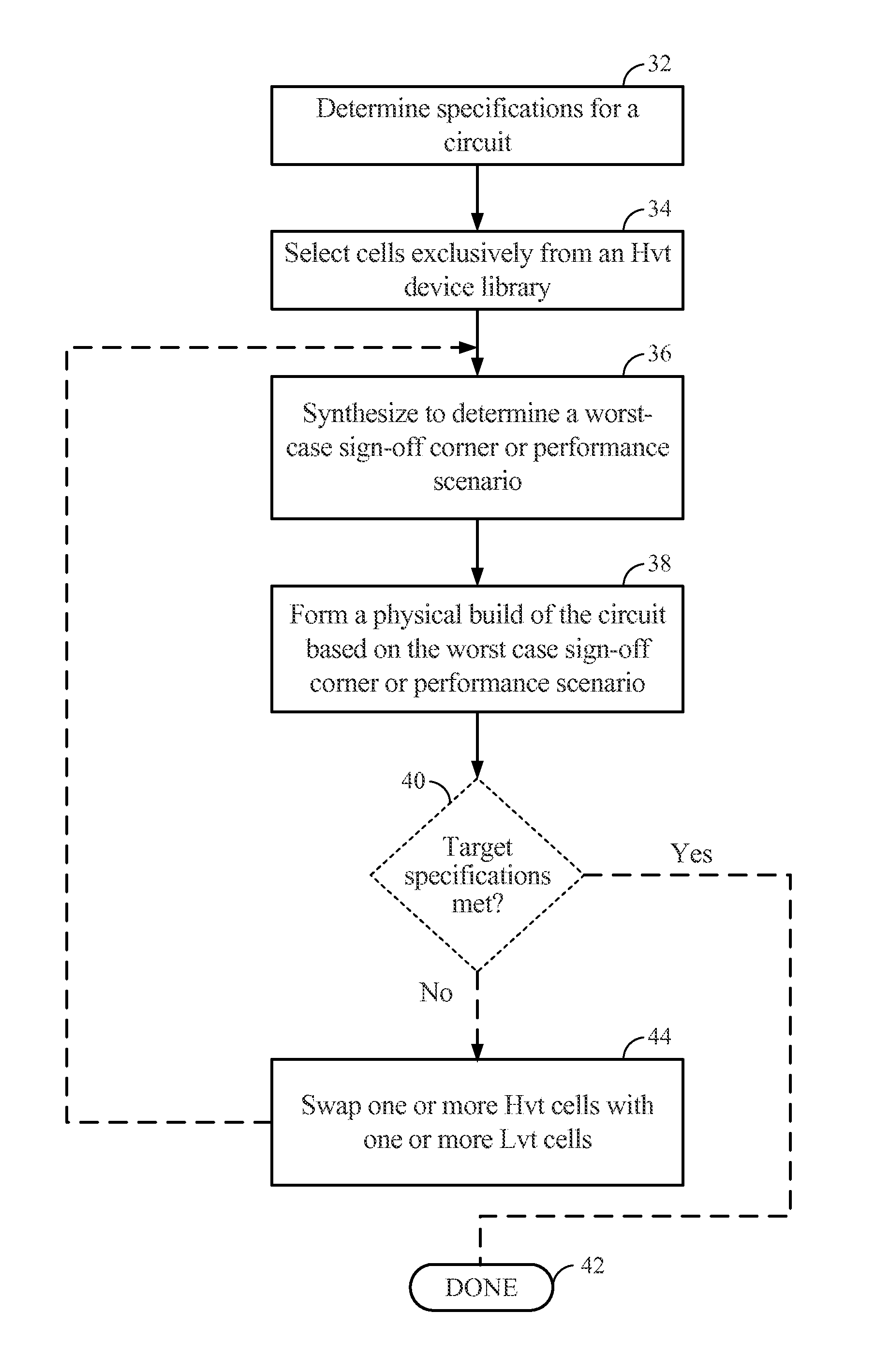
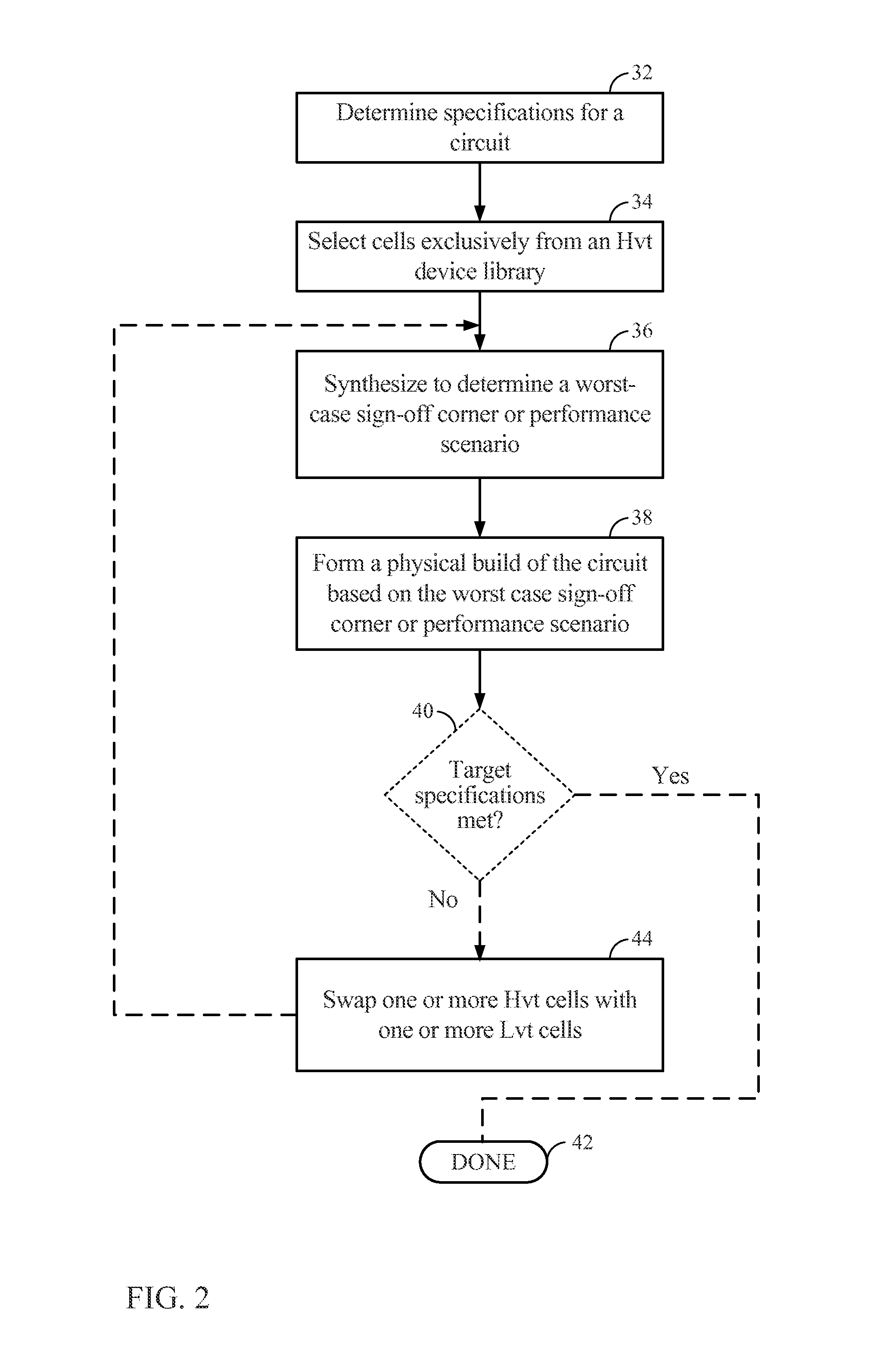
[0023]With reference now to the drawing figures, several exemplary embodiments of the present disclosure are described. The word “exemplary” is used herein to mean “serving as an example, instance, or illustration.” Any embodiment described herein as “exemplary” is not necessarily to be construed as preferred or advantageous over other embodiments.

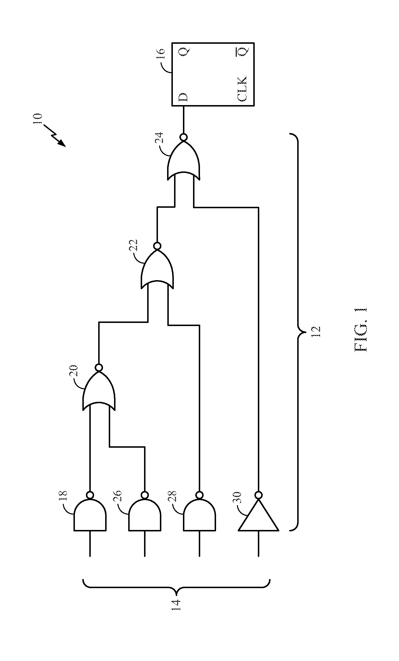
[0024]Embodiments disclosed in the detailed description include methods and circuits for optimizing performance and power consumption in a circuit design and circuit employing lower threshold voltage (Vt) (“Lvt”) cells and devices. The circuit layout and circuit employ one or more Lvt cells. Lvt cells are employed to increase performance (i.e., speed) of the circuit. However, Lvt cells have higher current leakage profiles as compared to nominal Vt (Nvt) and higher Vt (Hvt) cells, which leads to increased power consumption. To receive the benefit of Lvt cell performance while reducing or minimizing the tradeoff of higher leakage current in ...


PUM


Abstract

Methods and circuits for optimizing performance and power consumption in a circuit design and circuit employing one or more lower threshold voltage (Lvt) cells or devices are described. A base supply voltage amplitude is determined for providing operating power for the circuit. The base supply voltage amplitude is a low or lowest voltage level that still satisfies a performance specification for the circuit. Providing a low or lowest base supply voltage level reduces or minimizes the standby (i.e., non-switching) power consumption in the Lvt device(s) since current leakage is reduced as the supply voltage level is reduced. Reducing the supply voltage level used to power the Lvt device(s) also reduces active power consumption for the circuit as well. Thus, total power consumption is optimized or reduced while still receiving the benefit of using Lvt devices to optimize or increase performance of a circuit layout and circuit.

Description

BACKGROUND[0001]I. Field of the Disclosure[0002]The technology of the present application relates generally to cell-based designs and circuits incorporating use of lower threshold voltage (Vt) (“Lvt”) devices and related methodologies to increase performance and reduce power consumption in a circuit.[0003]II. Background[0004]Semiconductor technology has evolved into using deep sub-micron geometries. Deep sub-micron geometries are generally those less than one-hundred (100) nanometers. Using deep sub-micron semiconductor devices (also called “sub-micron devices”) allows integration of more complex functionality into a smaller area. For example, sub-micron device technologies are used to produce complex system-on-a-chip (SOC) designs where size constraints are limiting. SOC designs may be used in portable devices, including but not limited to cellular phones, personal digital assistants (PDAs), laptop computers, other electronic devices, and the like, where size constraints are limiti...

Claims


Application Information

Patent Timeline
Patent Type & Authority Patents(United States)
IPC IPC(8): G06F17/50
CPCG06F17/5068G06F2217/84G06F17/505G06F2217/78G06F17/5045G06F2119/12G06F30/39G06F2119/06G06F30/30G06F30/327G06F30/337G06F30/398
Inventor CHUA-EOAN, LEW, G.
Owner QUALCOMM INC
Learn More