Powder based soft magnetic inductive component, and a method and a device for production thereof

a soft magnetic inductive component and powder technology, applied in the direction of magnetic core inductance, magnetic material, coil, etc., can solve the problems of limited design freedom of the product, inability to integrate components, and inability to integrate other components in the produced product, so as to reduce the electrical conductivity, reduce the cost, and reduce the effect of manufacturing cos

Inactive Publication Date: 2015-01-13
MAGNETIC COMPONENTS SWEDEN
View PDF15 Cites 1 Cited by
  • Summary
  • Abstract
  • Description
  • Claims
  • Application Information

AI Technical Summary

Benefits of technology

[0011]This can be compared with the most common method today to compact and give the final shape to a SMC component is to use uniaxial pressing, but also methods like injection moulding, isostatic pressing and extrusion are used. For uniaxial and isostatic pressing there is limited design freedom of the product and it is not possible to integrate components, i.e. sensors, electronic boards, directly in the pressing of the produced product. Extrusion is used to form the SMC but also this method does not allow integration of other components in the produced product. Extrusion also limits the design freedom of the product. Injection moulding allow some design freedom and the possibility to integrate components but the SMC is not compacted enough resulting in low permeability.
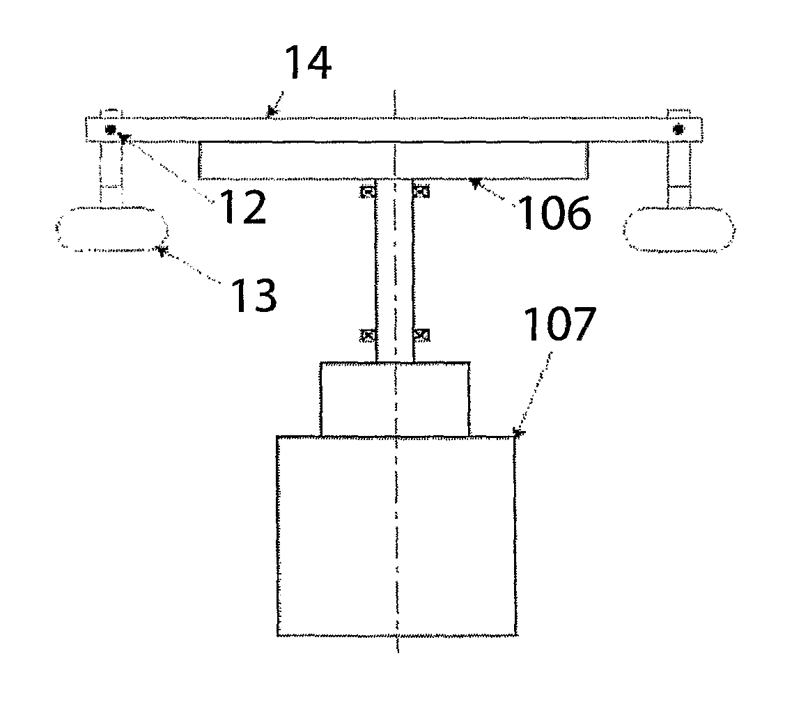
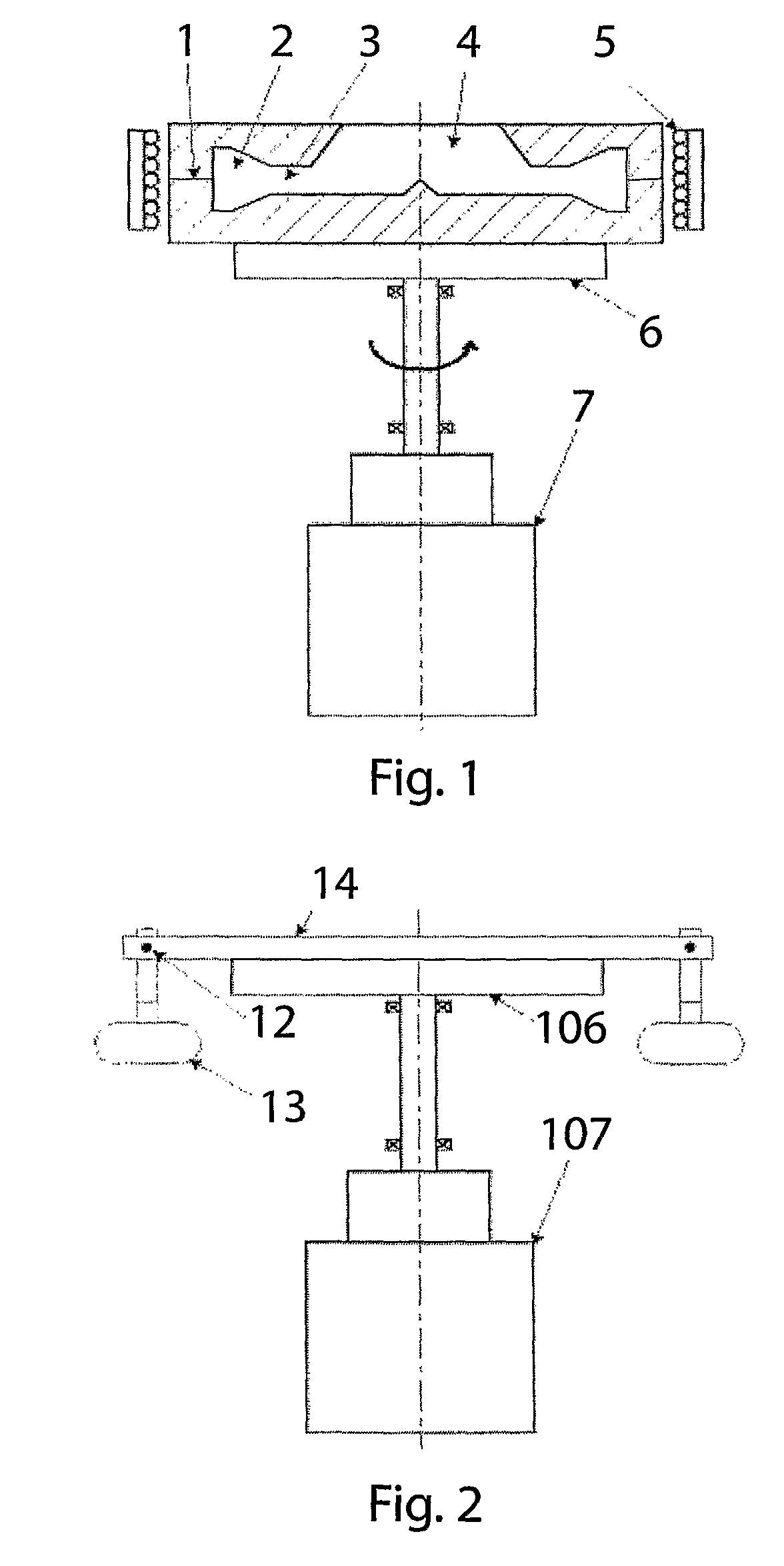
[0013]A process or apparatus in accordance with the invention enables an optimal manufacturing of soft magnetic powder composites, SMC. SMC consist of soft magnetic particles, sometimes coated to minimize electrical conductivity, and a binder, preferably a polymer. The invention is based upon rotational moulding, which is a production method mainly used in the plastics industry. An inventive apparatus may comprise one or several mould cavities mounted on carriers that can be rotated around one or several axes. Heating of the mould cavity, if needed, can for example be accomplished by induction heating, to keep cycle times short, while cooling, if needed, can be accomplished by water spray or by air. The mould cavity may be filled stationary or during rotation. The mould cavity may even be filled during rotation, with the polymer first and the metal particles after that. The physical conditions during the process will provide for optimal mixing proportions. During rotation, the heavier metal particles will be pushed outwards from the spinning centre, due to the centrifugal forces, while the polymer with a lower density will be pushed inwards, towards the centre of rotation.

Problems solved by technology

For uniaxial and isostatic pressing there is limited design freedom of the product and it is not possible to integrate components, i.e. sensors, electronic boards, directly in the pressing of the produced product.
Extrusion is used to form the SMC but also this method does not allow integration of other components in the produced product.
Extrusion also limits the design freedom of the product.
Injection moulding allow some design freedom and the possibility to integrate components but the SMC is not compacted enough resulting in low permeability.

Method used


Image

  • Powder based soft magnetic inductive component, and a method and a device for production thereof
  • Powder based soft magnetic inductive component, and a method and a device for production thereof
  • Powder based soft magnetic inductive component, and a method and a device for production thereof

Examples


examples

[0045]An electro magnetic energy converter is characterized by one or several electric circuits oriented in a fashion that they mutually exists in the magnetic fields originating from the current circulating in the electric circuits.

[0046]A soft magnetic structure can be used to enhance the capacity to conduct the magnetic flow around the circuits. The structure can consist of parts that are fixed or movable relative the circuits and the structure can also contain hard magnetic materials. When the magnetic flux is varying, the soft magnetic conductors are submitted to induced voltage which drives currents which in turn cause resistive losses, i.e. eddy-current losses. Other losses are associated with the changes in magnetic flow, primarily hysteresis losses and anomalous.

[0047]The losses are jointly known as magnetization losses. In order to reduce the magnetization losses, the magnetic circuit is traditionally split up in thin layers (laminates) that are electrically isolated and o...


PUM

PropertyMeasurementUnit
thicknessaaaaaaaaaa
particle size distributionaaaaaaaaaa
temperaturesaaaaaaaaaa

Abstract

A process for production of a packed soft magnetic component, comprises the steps of:—preparing a rotational mold, consisting of at least one mold cavity connected to a driven rotational axle, arranging a coil in the mold, filling the at least one mold cavity with a binder and a soft magnetic, metallic material in the form of a powder,—driving the axle for rotation of said at least one mold, whereby the soft magnetic, metallic material is packed by centrifugal forces to one side of said at least one mold cavity, mixed with the binder, thus forming a component comprising a soft magnetic composite with a coil embedded therein.

Description

TECHNICAL FIELD[0001]The present invention relates to the field of soft magnetic composites, and in particular to a process and an apparatus for manufacture of components consisting of soft magnetic composites. The invention also relates to products directly obtainable with such a method.TECHNICAL BACKGROUND[0002]A major part of today's advanced industrial products use some sort of electro magnetic energy converters, for example electrical motors, loudspeakers, microphones, sensors and actuators for opening / closing slides (e.g. DVD players), feeding bank notes (cash dispensers) etc.[0003]Almost all of these are standard motors / components of very conventional type where the production methods and possibilities of integrating components within a product haven't been developed much during the last century.[0004]Conventional motor manufacturing involves the punching and stacking of transformer sheets. Since the cost of punches is high, the production volumes must be considerable to have...

Claims


Application Information

Patent Timeline
Patent Type & Authority Patents(United States)
IPC IPC(8): B22F3/06B22F5/10B29C41/04C22C33/02H01F1/147H01F1/26H01F41/02
CPCB22F3/06B22F5/106B29C41/042C22C33/0257H01F1/26H01F41/0246C22C2202/02H01F1/14766B29C33/0016B29C41/045B29C41/20B29K2105/203B29K2995/0008B29C41/047B29C70/323B29C70/326H01F1/28
Inventor ALAKULA, MATS
Owner MAGNETIC COMPONENTS SWEDEN
Why Eureka
Try Eureka