
Thermally mounting electronics to a photovoltaic panel

a photovoltaic panel and electronic technology, applied in the direction of electrical apparatus construction details, pv power plants, semiconductor devices, etc., can solve the problems of affecting the overall conversion efficiency of solar power systems, affecting the convective and radiative transfer of heat generated by electronic components to the surrounding air, and being expensive to fabricate, etc., to achieve the effect of enlarged siz

Active Publication Date: 2015-01-13
SOLARNATIVE GMBH
View PDF9 Cites 4 Cited by
  • Summary
  • Abstract
  • Description
  • Claims
  • Application Information

AI Technical Summary

Benefits of technology

The present invention relates to an electronics assembly for a photovoltaic panel which efficiently uses the photovoltaic panel as a heat sink for heat produced by the electronic components. The assembly includes a thermally conductive substrate with one or more electronic components mounted on it. The cover of the assembly is made of a thermally conductive material and overcomes the problem of dirt clogging. The assembly also uses an intermediate heat sink and increases the heat dissipating surface area for efficient heat transfer to the photovoltaic panel. The size of the contact area should be carefully controlled to avoid excessive temperature increase in the photovoltaic panel. Overall, the invention provides a simple, low cost, well-defined and predictable system for cooling electronic components on photovoltaic panels.

Problems solved by technology

One problem of these known cooling schemes relates to the fact that—especially when mounted on a roof for an extended period of time—the space between the PV panel and the roof and the space between the cooling structures of the connection module may easily become clogged with dirt (e.g. twigs, leafs, etc.) thereby negatively affecting the convective and radiative transfer of heat generated by the electronic components to the surrounding air.
As a consequence, the electronics in an electronics module may become too hot so that it may break down, may cause ageing effects and / or may cause drift in the electronics, thereby negatively affecting the overall conversion efficiency of the solar power system.
A further problem relates to the fact that the cooling structures necessary for providing sufficient convective heat transfer are relatively complex structures, typically made out of aluminium or aluminium alloys and may thus be expensive to fabricate.

Method used


Image

  • Thermally mounting electronics to a photovoltaic panel
  • Thermally mounting electronics to a photovoltaic panel
  • Thermally mounting electronics to a photovoltaic panel

Examples


Embodiment Construction

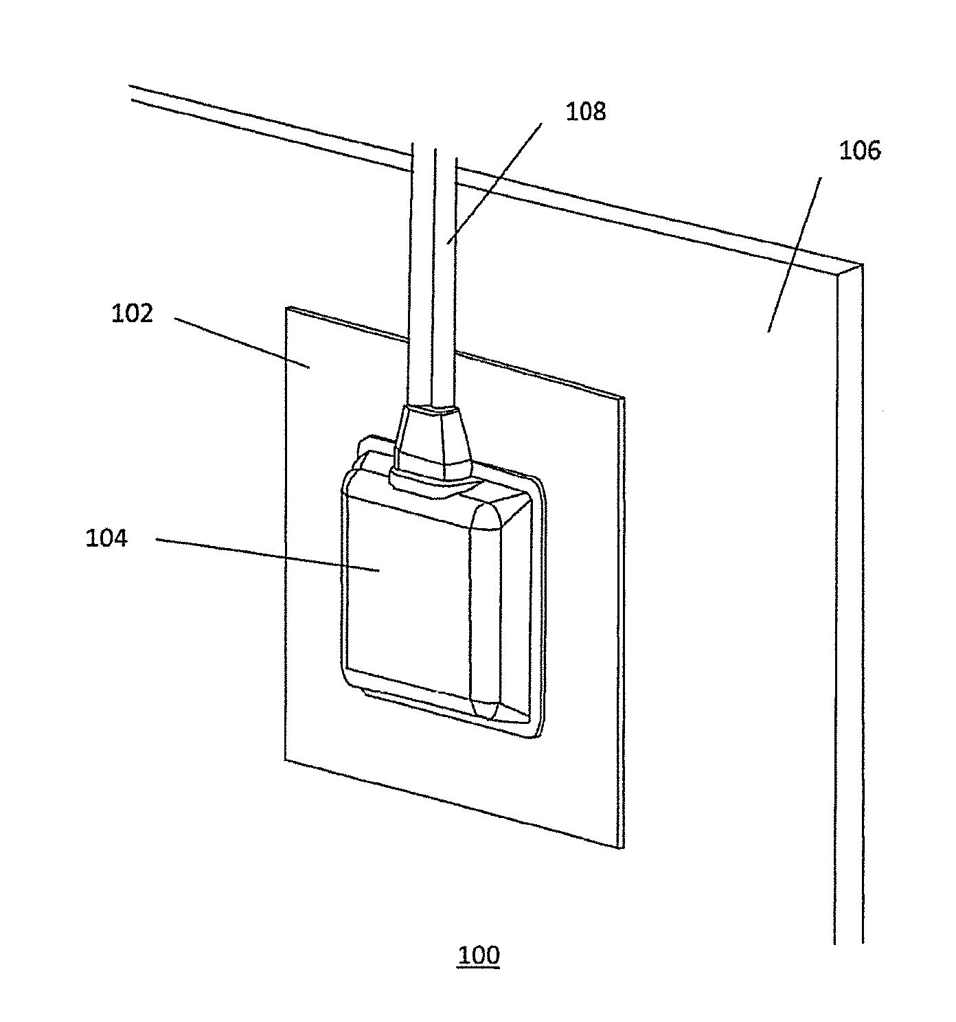
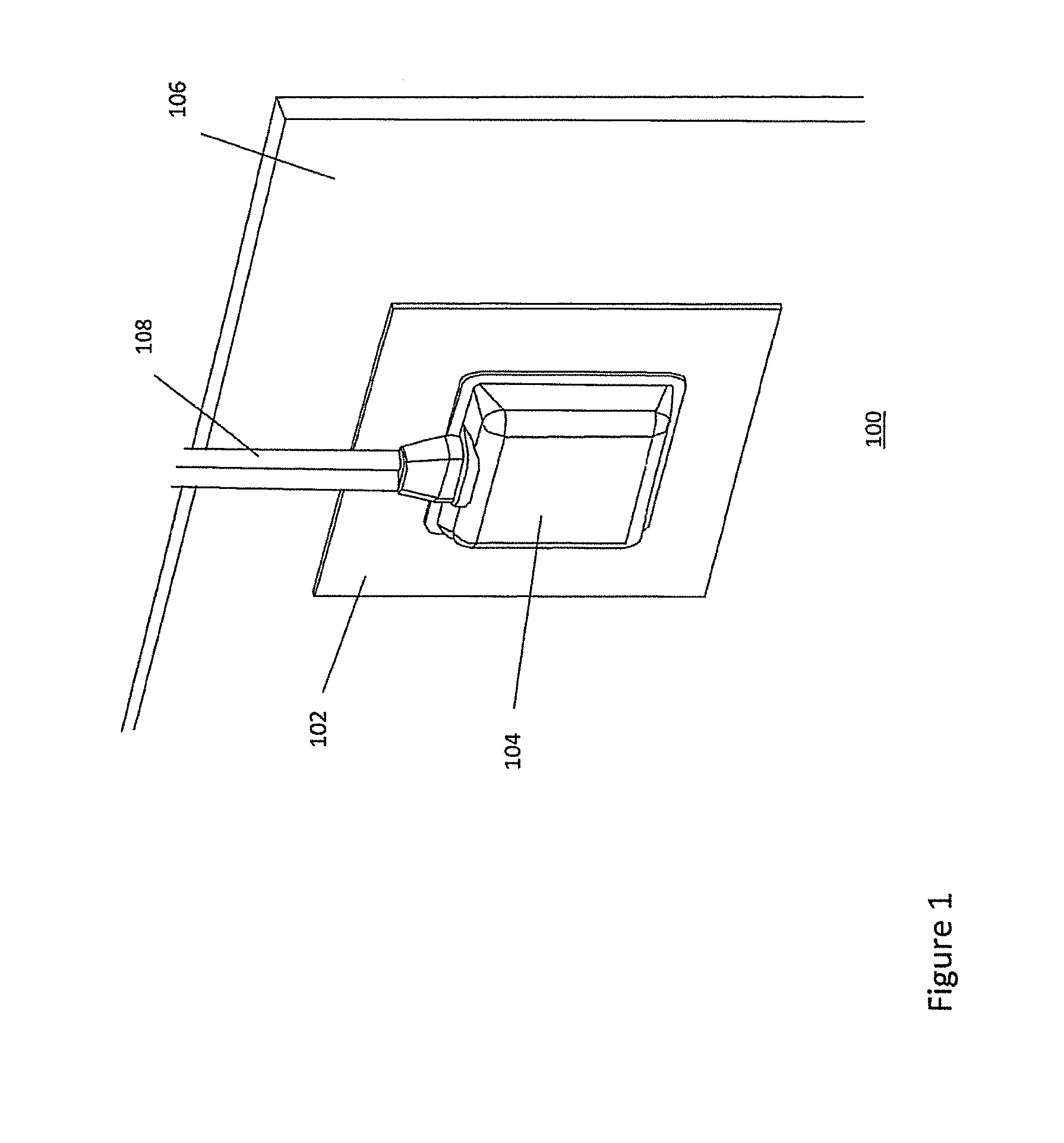
[0032]Referring now in greater detail to the drawings, FIG. 1 depicts a schematic of an exemplary electronics assembly 100 for a photovoltaic panel according to one embodiment of the invention. In this embodiment, the electronics assembly or module may comprise a substrate 102 of a material with a medium or high thermal conductivity such as a metal e.g. stainless steel 16-27, steel 50, aluminum 220, aluminum alloys (e.g. with Cu) 120-180, gold 318, silver 429 and boron nitride (BN) 600 (in W / (mK)). Other materials however are also possible. For example, the substrate may be of a polymer with a high thermal conductivity. In one embodiment, the substrate may be a Metal Clad PCB (MCPCB). Such substrate comprises a metal sheet (Aluminum, Steel, Copper) of 1-2 mm, a 0.05-0.5 mm isolation layer and a conductive metallic (typically Copper) pattern on top of the isolation layer.

[0033]The substrate 102 may be a thin, flat substrate in one embodiment which may be mounted onto the back of a PV...


PUM


Abstract

An electronics assembly for a photovoltaic panel includes a substrate of a thermally conductive material, wherein the substrate defines a thermal contact area for thermally contacting the electronics assembly to a photovoltaic panel; and at least one electronic component provided on the substrate and in thermal contact with the substrate, so that when the electronics assembly is in thermal contact with the photovoltaic panel. The thermal contact provides a heat conductive channel between the at least one electronic component and the photovoltaic panel, wherein the heat conductive channel enables the electronics assembly to use the photovoltaic panel as a heat sink for heat produced by the at least one electronic component.

Description

CROSS REFERENCE TO RELATED APPLICATIONS[0001]This application is a continuation-in-part (CIP) of International Application PCT / EP2010 / 059860, filed Jul. 9, 2010, which claims priority to European Patent Application No. 09 165 077.0, filed Jul. 9, 2009.FIELD OF THE INVENTION[0002]The invention relates to an electronics assembly for a photovoltaic panel and, in particular, though not exclusively, to an electronics assembly for use in thermal contact with a photovoltaic panel and a solar panel system comprising such electronics assembly.BACKGROUND OF THE INVENTION[0003]In order to reduce the amount of energy required from non-renewable energy sources, renewably energy sources, in particular solar energy, are the object of intense research. Currently a lot of effort is directed towards improving the overall conversion efficiency of a solar power system in order to make such systems ready for large-scale, commercial applications.[0004]The basic building block of a solar power system is a...

Claims


Application Information

Patent Timeline
Patent Type & Authority Patents(United States)
IPC IPC(8): H01L31/052H05K7/20H01L31/048
CPCH01L31/048H01L31/0488H02S40/34H02S40/345Y02E10/50
Inventor OLDENKAMP, HENDRIKDE JONG, IRENE JOHANNA
Owner SOLARNATIVE GMBH
Learn More