System, method and apparatus for unsupervised adaptation of the perception of an autonomous mower

a technology of an autonomous mower and a system, which is applied in the direction of process and machine control, distance measurement, instruments, etc., to achieve the effect of improving the state of the art and improving the ability of autonomous mowers

Active Publication Date: 2015-02-17
HONDA RES INST EUROPE
View PDF8 Cites 17 Cited by
  • Summary
  • Abstract
  • Description
  • Claims
  • Application Information

AI Technical Summary

Benefits of technology

[0018]In view of the above-mentioned disadvantages of the commercially available and the proposed autonomous mowers, the present invention is intended to improve the state of the art. In general the present invention aims to provide an improved system and method for controlling an autonomous mower, and presents a mower with improved autonomous mowing capabilities. A much desired improvement is to control the mower over a broader range of varying light conditions in comparison to the state of the art.

Problems solved by technology

However, such mowers will still drive over small obstacles (like e.g. cellular phones, hoses or garden tools) lying on the grass, since such small obstacles are neither indicated by the border wire nor detected by the bump or sonar sensor.
On the one hand side this can cause severe damage to the mowing blades, and on the other hand side this can also damage the small obstacles.
Furthermore, most available autonomous mowers bump into objects, before they turn away, even those mowers that additionally use sonar sensors.
This ultimately leads to many scratches on the outer shell of the mowers.
However, the technique is limited to certain operation limits of the camera sensor.
However, the patent application is limited to good lighting conditions.
The patent, however, does not intend to apply the technique to autonomous lawn mowing.
However, no scene specific adaptation is carried out.
“Automatic Camera Exposure Control, N. Nourani-Vatani and J. Roberts, Australasian Conference on Robotics and Automation (December 2007)” describes an automatic exposure control for an omni-camera, which also features a mask for excluding the dark parts of a mirror support, which would lead to a wrong control due to bias.
However, the paper does not target for an optimal camera control for lawn mowers.
As a consequence the approaches fail under varying illumination conditions that occur in real-world gardens.
However, none of the known prior art considers the image processing, camera control and motor control as a holistic problem.
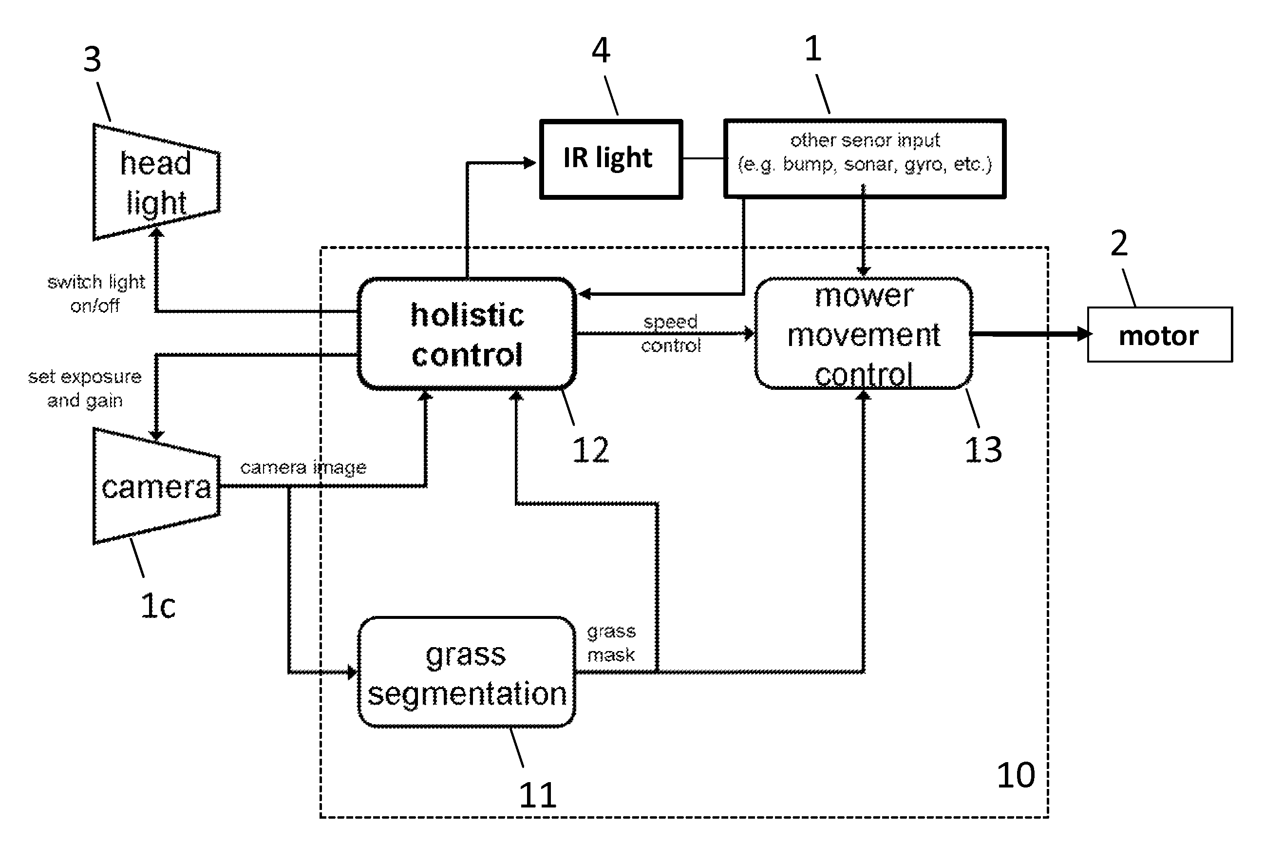
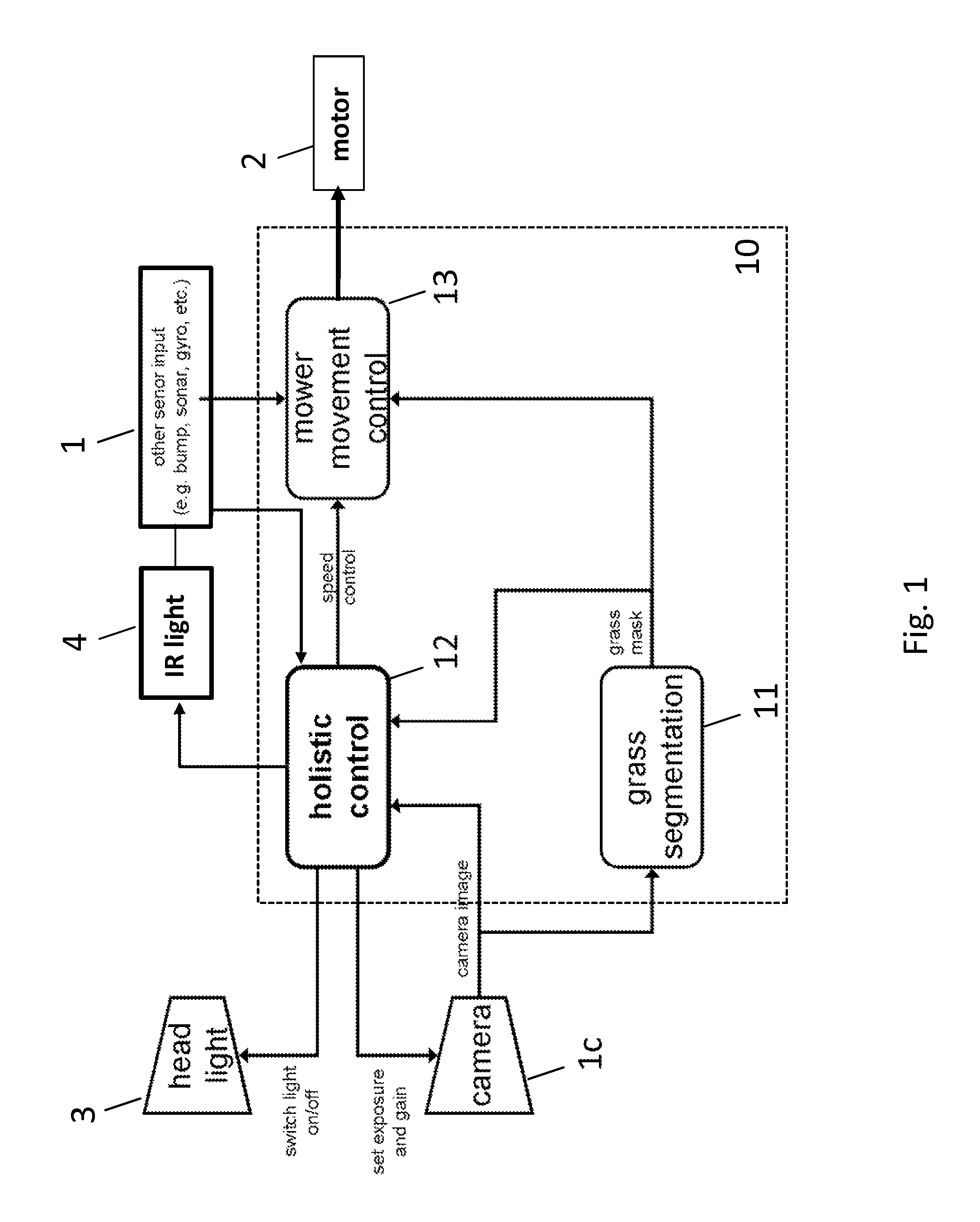
First, a mower driving control (motor control module) is adapted in a way to alleviate the limits of the camera sensor. Nowadays cameras struggle to cover the wide range of illumination conditions that occur in real-world scenarios. Two major problems are low light conditions and strong intensity contrast. The first problem requires the camera to use large exposure times, which leads to motion blur when the camera is moving, or high gain values, which leads to an increase in camera noise. Thus in both cases the signal quality is bad. The present invention alleviates this problem by adequately reducing the movement speed of the mower. This enables to use larger exposure times without a deteriorated camera signal due to motion blur. The idea is that the higher the exposure times of the camera needs to be, the slower the mower is moving. The solution to the second problem is that when the mower approaches a strong contrast, the movement speed of the mower is reduced so that the camera has enough time to adapt, e.g. the exposure time, to the strong lighting difference. If this is not enough, the mower stops and captures two images with different exposure times, in order to generate a high dynamic range, HDR, image, covering a much larger intensity range.
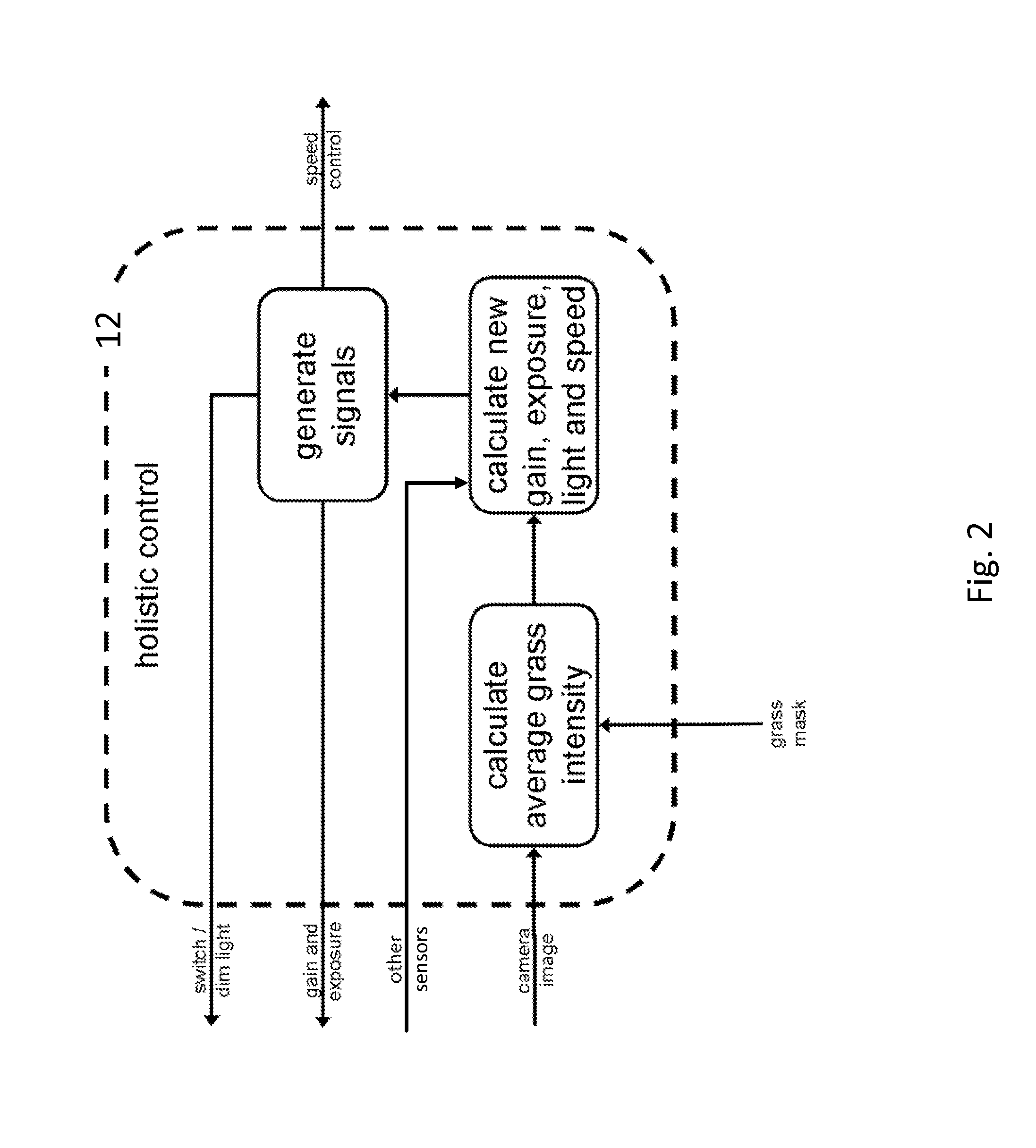
Second, the invention employs an intelligent control of the camera exposure and gain tailored specifically for the application of lawn mowing. Instead of adapting the parameters of the camera by taking all pixel intensities in the current image into account, only the intensity of grass pixels is taken into account, in order to optimize in particular the visibility of grass areas. This leads to more robust grass detection, since the grass alone does not have as large a dynamic range as the whole garden scene.
Third, the invention uses a different target to optimize the camera signal quality. While state of the art approaches target at a mean pixel intensity of 0.5 for intensity ranges of [0 . . . 1] (i.e. from 0 to 1) (or 125 for intensity ranges of [0 . . . 255]) the present invention targets at a logarithmic equilibrium of the intensities within the dynamic range of the camera sensor. This means that one can double the irradiance exactly as often as halving it, before the major amount of the camera pixels reach the sensing limit. Thus, the camera can react well to both an increase in irradiance (e.g. driving from a shadow area into a sunny area) as to a decrease in irradiance (e.g. driving from a sunny area into a shadow area). Irradiance is the power of electromagnetic radiation per unit area (i.e. the radiative flux) incident on a surface. The radiant emittance or radiant exitance is the power per unit area radiated by a surface.

Method used


Image

  • System, method and apparatus for unsupervised adaptation of the perception of an autonomous mower
  • System, method and apparatus for unsupervised adaptation of the perception of an autonomous mower
  • System, method and apparatus for unsupervised adaptation of the perception of an autonomous mower

Examples


Embodiment Construction

[0054]The present invention relates to an automatic mower, which has at least one camera 1c, preferably a plurality of other sensors 1, like a sonar sensor is or infrared sensor 1i, at least one propulsion system, like a motor 2, and optionally at least one a head light or lighting means 3 and / or an IR light. Preferably, the mower is a lawn mower, but it can also be some other kind of mower. The mower is equipped with a control system 10.

[0055]The control system 10 of the mower has a module 11 for grass detection and a module 13 for motor control (i.e. control of the mower movement), which uses the output of the grass detection module 11 for issuing motor commands that for example allow the mower to avoid obstacles in its path or to navigate to a certain target, e.g. a home base for recharging the mower.

[0056]The control system 10 further comprises an intelligent holistic control module 12, which optimizes in particular the camera signal quality for grass detection by means of adapt...


PUM


Abstract

The present invention presents a method and system for an autonomous mower attached with a camera, wherein the control of the parameters of the camera and the control of the mower movement and grass detection are optimized holistically during operation. The present invention mitigates the camera sensing limits by adapting the movement speed of the mower. Furthermore, the camera control optimizes the visibility of grass by using the grass mask of a grass segmentation to calculate updated exposure, gain and aperture values only from grass pixels. The grass segmentation tracks changes in the grass color that are caused by illumination differences. Optionally, the system is equipped with a head light used to further improve the camera signal quality in conjunction with the control of the camera parameters and the movement speed of the mower.

Description

CROSS REFERENCE TO RELATED APPLICATIONS[0001]This application claims the benefit of priority to European Application No. 12152452.4 filed on Jan. 25, 2012.BACKGROUND[0002]1. Field[0003]The present invention relates to a system and method for controlling an autonomous mower, e.g. lawn mower, and for adapting its perception, i.e. the combined sensing of the mower's environment (“environment” being the input field of the sensor(s)). In particular the present invention is for performing a combined control of sensor parameters, motor commands, and camera image computations of the autonomous mower. The present invention further relates to an autonomous mower equipped with said control system.[0004]2. Description of Related Art[0005]Autonomous or robotic mowers, e.g. lawn mowers, are an increasing market. Such mowers typically mow a lawn autonomously in a random brute-force fashion cutting only small pieces of grass in every run. Small grass pieces fall into the sod, thereby fertilizing th...

Claims


Application Information

Patent Timeline
Patent Type & Authority Patents(United States)
IPC IPC(8): G01C22/00A01B69/00A01D34/00A01D34/04
CPCA01D34/008A01D34/04A01D34/00A01B69/001G05D2201/0208G05D1/0274G05D1/0246G05D1/0221G06V20/10
Inventor EINECKE, NILSFRANZIUS, MATHIAS
Owner HONDA RES INST EUROPE
Why Eureka
Try Eureka