Vacuum-pressure spray-drying method and vacuum-pressure spray-drying device

a vacuum-pressure spray and spray-drying technology, which is applied in the direction of lighting and heating equipment, separation processes, furniture, etc., can solve the problems of difficult blowing off fermented milk powder produced by drying, increased apparatus size, poor heat transfer efficiency, etc., and achieves efficient drying and powder

Active Publication Date: 2015-03-03
TANABE IND
View PDF31 Cites 6 Cited by
  • Summary
  • Abstract
  • Description
  • Claims
  • Application Information

AI Technical Summary

Benefits of technology

[0044]According to the vacuum-pressure spray-drying method and the vacuum-pressure spray-drying apparatus of the present invention, it is possible to efficiently dry and powder the liquid raw material containing a substance susceptible to heat denaturation, such as a food raw material and a medicine raw material.

Problems solved by technology

However, in this method, the placed object to be dried is subjected to contact and heat exchange with the depressurized superheated vapor.
Accordingly, when the object to be dried is a liquid raw material, it is difficult to ensure a large evaporating heating surface, and there is a problem in that the apparatus is increased in size in order to ensure the large evaporating heating surface.
However, also in this method, it is necessary that the object to be dried be mixed with the fluidized particles in the fluidized bed drying apparatus main body so as to form the fluidized state, and hence this method is inappropriate as a method of drying and powdering a liquid raw material as a substance susceptible to heat denaturation.
Accordingly, there is a problem in that a heat transfer efficiency is poor.
However, in this method, due to lack of quantity of the air that is introduced into the drying tower so as to flow in the drying tower, it is difficult to blow off the fermented milk powder produced by drying.
Accordingly, there is a problem in that this method is inappropriate for high-volume production in spite of its appropriateness for low-volume production.
However, in this method, the heating gas is formed of non-liquefied gas (which is non-condensable) such as the air and nitrogen gas.
Accordingly, it is difficult to keep a constant degree of vacuum of the inside of the dryer main body, and a large quantity of gas is required in order to ensure a heat quantity necessary for drying because the heating gas has a relatively small heat capacity.
Further, the hot air introducing portion for introducing the heating gas is separated from the two fluid nozzle, and hence heat of the heating gas is not sometimes transferred efficiently to the atomized raw material liquid.
Therefore, there is a problem in that the apparatus is increased in size and it is difficult to perform powdering in a short period of time.

Method used


Image

  • Vacuum-pressure spray-drying method and vacuum-pressure spray-drying device
  • Vacuum-pressure spray-drying method and vacuum-pressure spray-drying device
  • Vacuum-pressure spray-drying method and vacuum-pressure spray-drying device

Examples


first embodiment

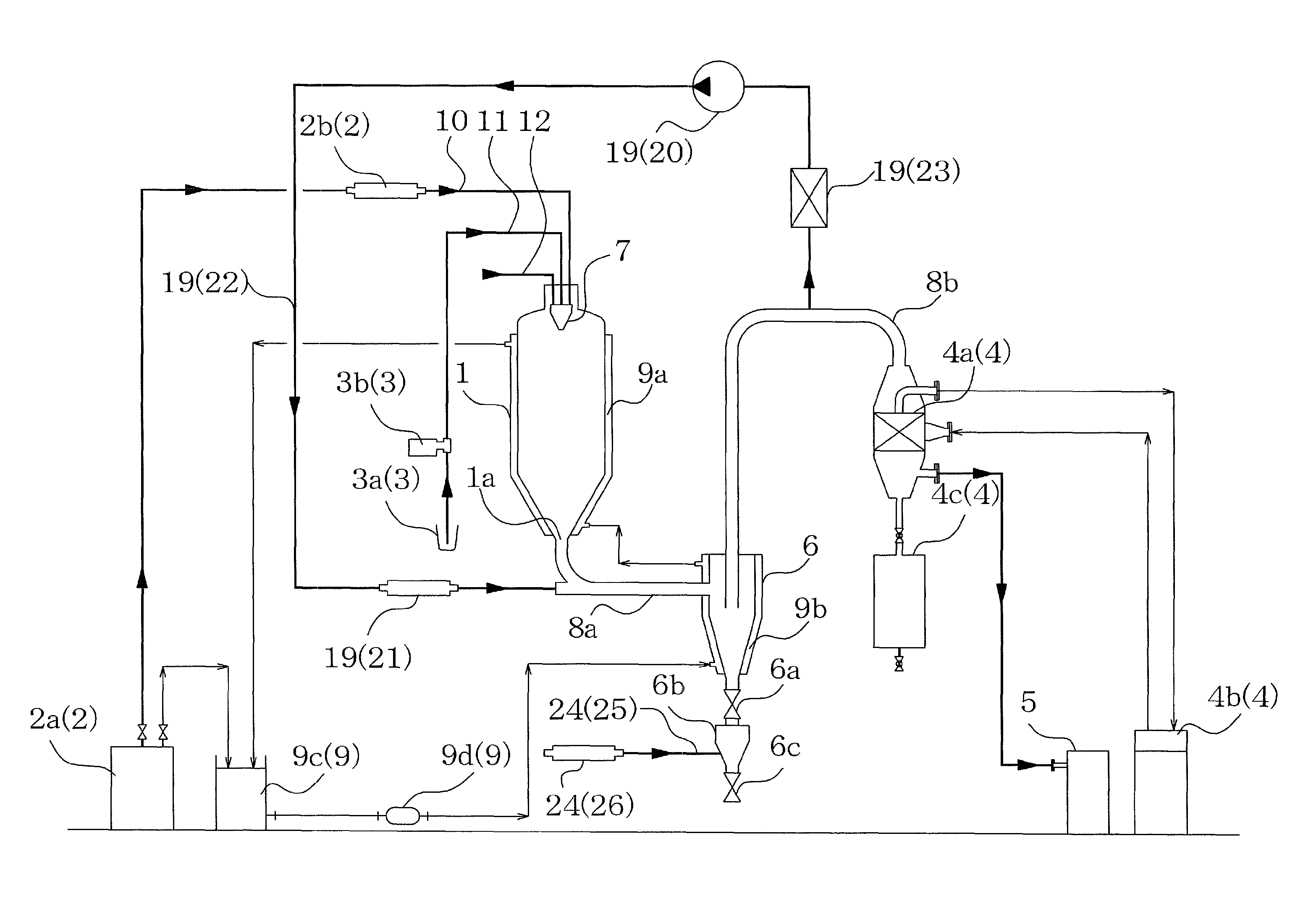
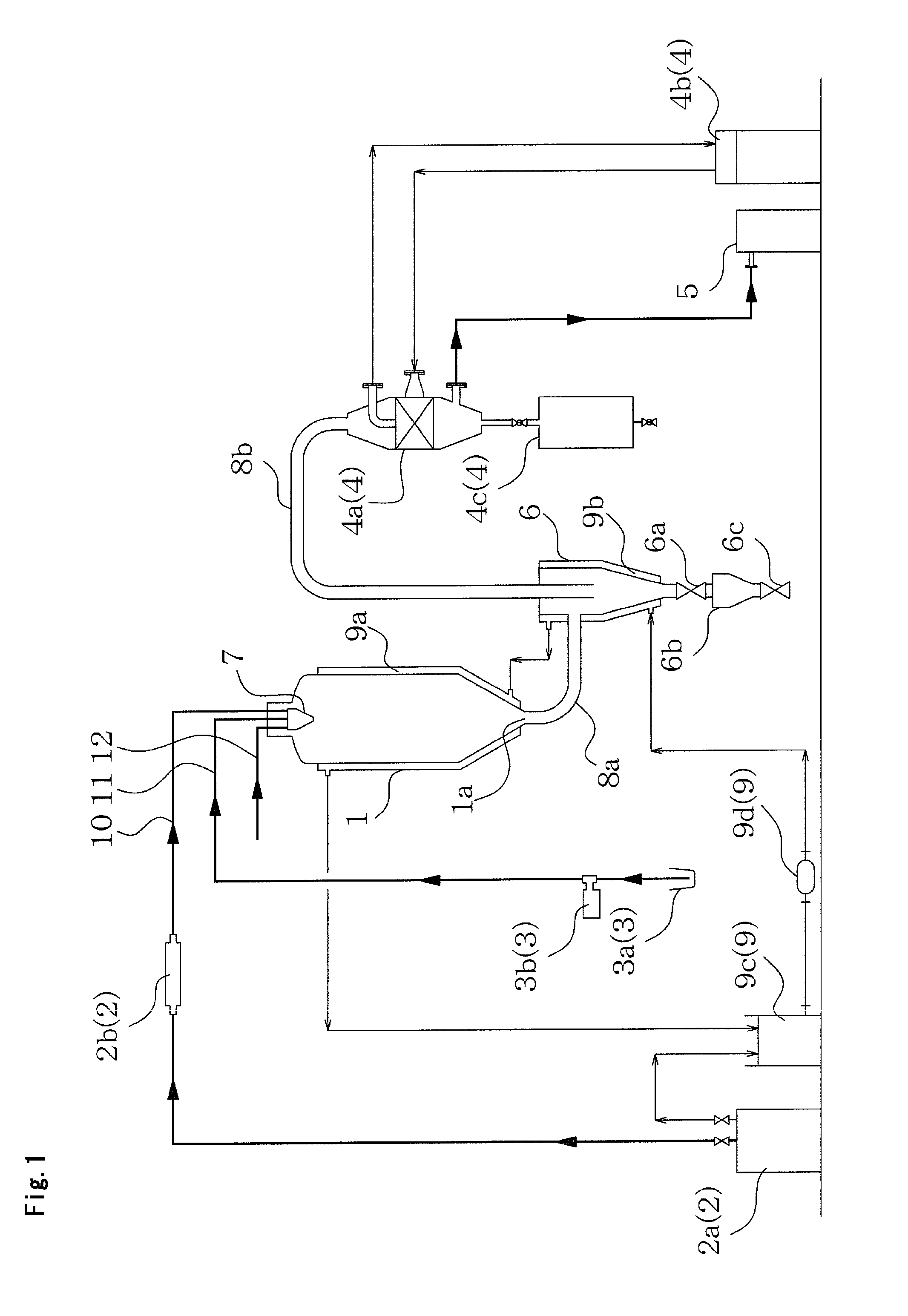
[0059]FIGS. 1 and 2 illustrate a vacuum-pressure spray-drying method and a vacuum-pressure spray-drying apparatus according to a first embodiment of the present invention.

[0060]In the first embodiment, the vacuum-pressure spray-drying apparatus includes an evaporator (apparatus main body) 1, superheated water vapor supplying means 2, liquid raw material supplying means 3, cooling means 4, a vacuum pump (pressure reducing means) 5, and a cyclone collector (product collecting means) 6.

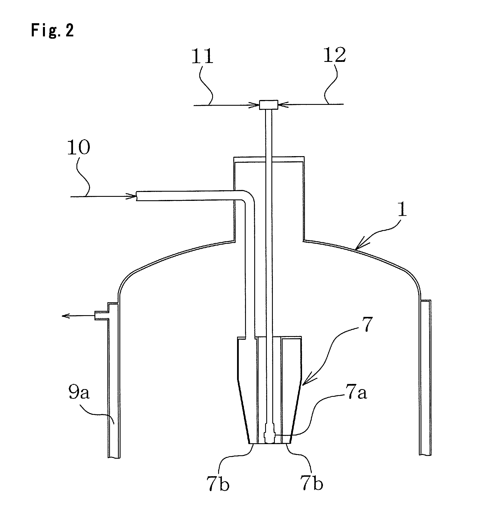
[0061]The evaporator 1 is formed of a container that is kept at reduced pressure. The evaporator 1 includes a spray nozzle 7 formed at an upper end thereof, and an outlet 1a formed in a lower end thereof. The superheated water vapor supplying means 2 supplies a superheated water vapor to the spray nozzle 7, and includes a boiler 2a for generating a water vapor, and a heater 2b for heating the water vapor generated by the boiler 2a to change the water vapor into the superheated water vapor. The liquid raw...

second embodiment

[0072]FIGS. 3 and 4 illustrate a vacuum-pressure spray-drying method and a vacuum-pressure spray-drying apparatus according to a second embodiment of the present invention.

[0073]Unlike the above-mentioned first embodiment, the second embodiment uses, as the apparatus main body, the evaporator 1 in which a heat exchanging section 13 as an upper part and a product collecting section 14 as a lower part are separably coupled together.

[0074]The spray nozzle 7 for supplying the liquid raw material and the superheated water vapor from a side of the heat exchanging section 13 in an inner peripheral direction of an inner wall surface of the heat exchanging section is provided to a side wall of an upper portion of the heat exchanging section 13. Further, at an upper end portion of the heat exchanging section 13, the outlet 1a for discharging the exhaust gas is formed. Further, a pipe 8c for directly transferring the exhaust gas into the cooling means 4 is provided to extend from the outlet 1a...

third embodiment

[0079]FIGS. 5 and 6 illustrate a vacuum-pressure spray-drying method and a part of a vacuum-pressure spray-drying apparatus according to a third embodiment of the present invention.

[0080]Unlike the above-mentioned first embodiment, the third embodiment adopts the following configuration as the spray nozzle 7.

[0081]That is, in the spray nozzle 7 according to the third embodiment, the spray port 7a, which is arranged at the center position of the spray nozzle 7, for spraying the liquid raw material, includes: a liquid raw material discharge hole 16 situated in a center portion thereof, for discharging the liquid raw material; an air discharge hole 17 situated on an outer side of the liquid raw material discharge hole 16 to surround the liquid raw material discharge hole 16 in a ring-shaped manner, for discharging heat-insulating air; and a saturated vapor discharge hole 18 situated on an outer side of the air discharge hole 17 to surround the air discharge hole 17 in a ring-shaped man...


PUM

PropertyMeasurementUnit
vapor temperatureaaaaaaaaaa
temperatureaaaaaaaaaa
vapor temperatureaaaaaaaaaa

Abstract

Provided are a novel vacuum-pressure spray-drying method and a novel vacuum-pressure spray-drying apparatus suitable for drying and powdering a liquid raw material containing a substance susceptible to heat denaturation, such as a food raw material and a medicine raw material. The vacuum-pressure spray-drying method and the like include: an apparatus main body, which is kept at reduced pressure and includes a spray nozzle; superheated water vapor supplying means for supplying a superheated water vapor to the spray nozzle; liquid raw material supplying means for supplying a liquid raw material to the spray nozzle; cooling means for cooling the superheated water vapor and a vapor resulting from volatilization of the liquid raw material being discharged from the apparatus main body, and then collecting, as condensed water; pressure reducing means for keeping an inside of the apparatus main body at the reduced pressure through the cooling means; and product collecting means for collecting a powder product produced in the apparatus main body. The vacuum-pressure spray-drying method and the like include: simultaneously spraying the superheated water vapor supplied from the superheated water vapor supplying means and the liquid raw material supplied from the liquid raw material supplying means through the spray nozzle into the apparatus main body so as to atomize the liquid raw material in the apparatus main body; and subjecting an atomized raw material, which is produced by atomizing the liquid raw material, to heat exchange with the superheated water vapor, to thereby dry and powder the liquid raw material.

Description

TECHNICAL FIELD[0001]The present invention relates to a vacuum-pressure spray-drying method and a vacuum-pressure spray-drying apparatus for drying and powdering a liquid raw material at reduced pressure. In particular, the present invention relates to, but is not particularly limited to, a vacuum-pressure spray-drying method and a vacuum-pressure spray-drying apparatus suitable for drying and powdering a liquid raw material obtained by dissolving or dispersing, into water or the like, a substance that is susceptible to heat denaturation and easily oxidized, decomposed, or degraded when being heated. Examples of the substance include lactic acid bacteria, a vitamin C, an aroma component of tea, heat-sensitive natural food, and a food raw material and a medicine raw material containing the above-mentioned components.BACKGROUND ART[0002]Hitherto, as a method of drying at low temperature a substance susceptible to heat denaturation, some technologies have been proposed.[0003]For exampl...

Claims


Application Information

Patent Timeline
Patent Type & Authority Patents(United States)
IPC IPC(8): F26B5/00A23C1/04A23L3/46B01D1/14B01D1/18B01D1/20B01J2/04F26B3/12F26B5/04
CPCB01D1/14A23L3/46B01D1/18B01D1/20B01J2/04F26B3/12F26B5/04A23C1/045
Inventor KITAMURA, YUTAKAYAMAZAKI, KAZUHIKOYAMANO, YOSHITSUGU
Owner TANABE IND
Why Eureka
Try Eureka